
MR sensor with back edge flux guide

Active Publication Date: 2013-02-28
HEADWAY TECH INC
View PDF9 Cites 7 Cited by
  • Summary
  • Abstract
  • Description
  • Claims
  • Application Information

AI Technical Summary

Benefits of technology

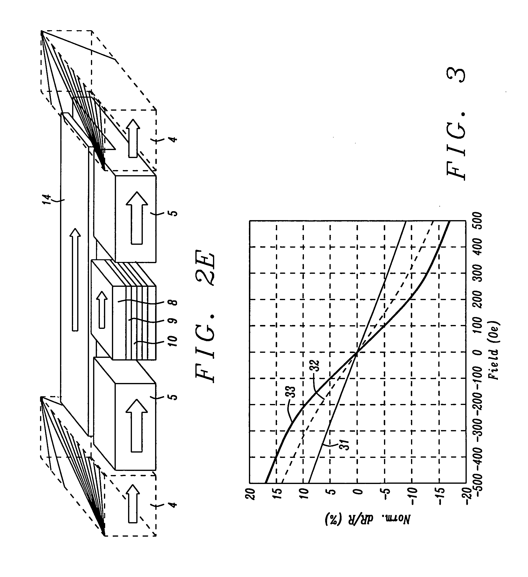
The invention provides a method to sense magnetic data at high densities without increasing noise and instability. This is achieved by partially etching away the free layer and replacing it with a magnetic flux guide structure that reduces demagnetization field and improves magneto-resistance ratio. The resulting device exhibits enhanced resolution and read-back signal, allowing better performance in densely recorded environments and optimizing sensor stability and sensitivity.

Problems solved by technology

However, with smaller sensor size, magnetic noise gets worse as does sensor stability.
This is, however, very hard to achieve in existing state-of-the-art TMR sensors.

Method used


Image

  • MR sensor with back edge flux guide
  • MR sensor with back edge flux guide
  • MR sensor with back edge flux guide

Examples


embodiments

Embodiment 1

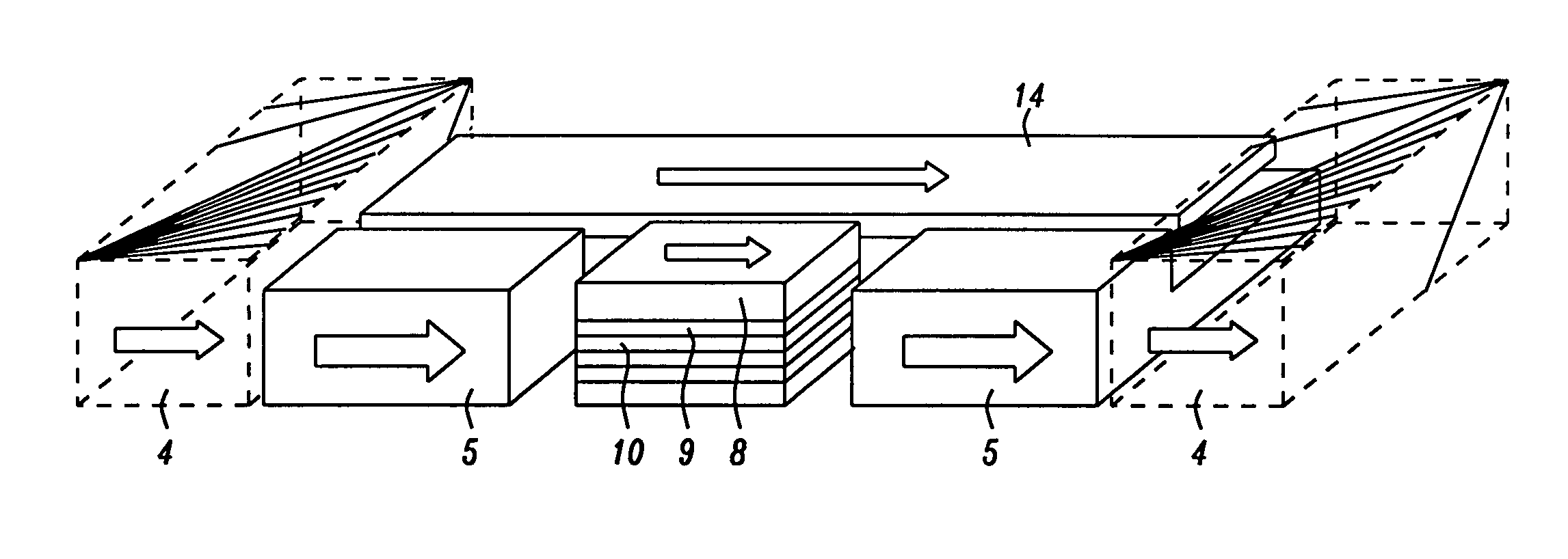
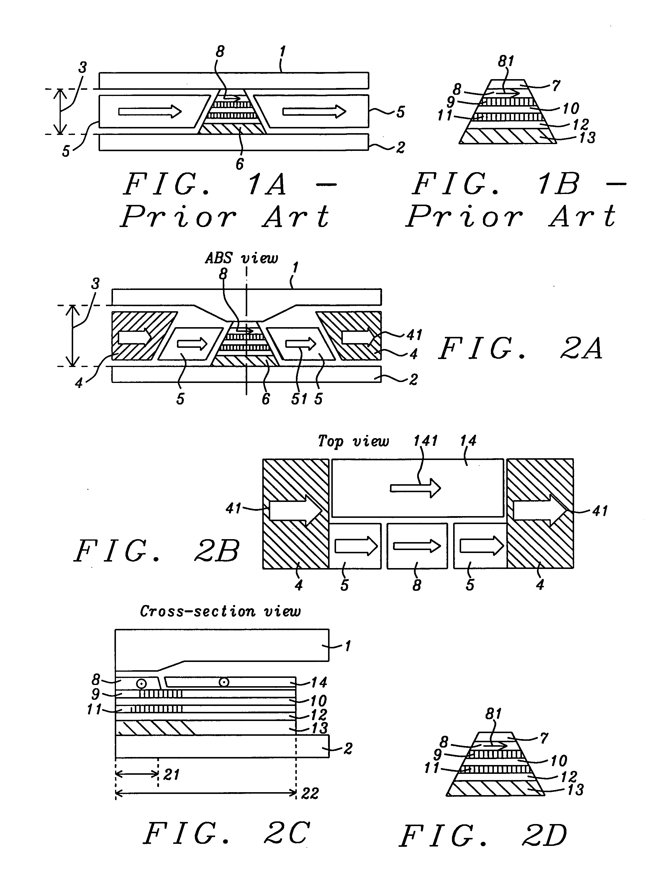
[0047]The structure shown in FIG. 2.

embodiment 2

[0048]The same as Embodiment 1 except that HB 4 as in FIG. 2 is in physical contact with HB 5 and FG layer 14. In this way, HB 4 stabilizes FG layer and HB 5 through direct exchange coupling.

embodiment 3

[0049]The same as Embodiment 1, except that HB 4 is no existent and FG 14 edge magnetizations are stabilized by synthetic-anti-ferromagnetic (SAF) structures. Layer 21 is Ru layer and layer 22 is another magnetic layer with opposite magnetization to FG 14 and forms SAF structure with FG 14 edge magnetization


PUM

PropertyMeasurementUnit
Thicknessaaaaaaaaaa
Thicknessaaaaaaaaaa
Thicknessaaaaaaaaaa

Abstract

An MR sensor, and a method for making it, is described. Part of the MR stack, from the free layer on up, is removed and then replaced by a flux guide. Additional stabilizing means for this flux guide are provided, either as hard bias or through exchange coupling.

Description

FIELD OF THE INVENTION[0001]The invention relates to the general field of sensing magnetically recorded data with particular reference to very high data densities.BACKGROUND OF THE INVENTION[0002]With an ever-increasing data areal density in hard disk drives (HDD), the magneto-resistive (MR) sensor that is used as the read-back element in HDDs is required to have correspondingly better spatial resolution while at the same time achieving reasonable signal-to-noise ratio (SNR). FIG. 1 shows the structure of a generic TMR (tunneling-magneto-resistive) head which is the main MR sensor structure used in state-of-the-art HDD.[0003]As seen in FIG. 1A, a generic TMR head has top and bottom reader shields 1 and 2 respectively, spaced distance 3 apart, hard bias (HB) magnets 5 on the sides and MR sensor stack 6 located between the reader shields. FIG. 1B shows conventional MR sensor stack 6 that includes free layer (FL) 8, tunneling barrier 9, reference layer 10, anti-parallel coupling layer ...

Claims


Application Information

Patent Timeline
IPC IPC(8): G01R33/09B32B37/14B32B38/08B32B38/10B32B38/00
CPCG01R33/098B32B37/02B32B38/10B32B2309/105B32B2457/08Y10T29/49044Y10T29/49048Y10T29/49043Y10T29/49052Y10T29/49046B32B2307/212
Inventor ZHOU, YUCHENSMYTH, JOELI, MINGARFUNKEL, GLEN
Owner HEADWAY TECH INC
Learn More