Permanent magnet rotor and permanent magnet motor

A permanent magnet rotor and permanent magnet technology, applied in the direction of magnetic circuit rotating parts, magnetic circuits, electrical components, etc., can solve the problems of motor failure, permanent magnet demagnetization, and motor performance degradation, so as to improve efficiency and reduce leakage Magnetic, to avoid the effect of non-operation

Inactive Publication Date: 2016-04-13
ZHUHAI GREE REFRIGERATION TECH CENT OF ENERGY SAVING & ENVIRONMENTAL PROTECTION
View PDF6 Cites 7 Cited by
  • Summary
  • Abstract
  • Description
  • Claims
  • Application Information

AI Technical Summary

Problems solved by technology

[0004] In the embodiment of the present invention, a permanent magnet rotor and a permanent magnet motor are provided to solve the problems in the prior art that the part of the permanent magnet close to the rotating shaft cannot be magnetized to a saturated state, resulting in a decrease in the performance of the motor, loss of magnetization of the permanent magnet and failure of the motor to operate. The problem

Method used


Image

  • Permanent magnet rotor and permanent magnet motor
  • Permanent magnet rotor and permanent magnet motor
  • Permanent magnet rotor and permanent magnet motor

Examples


Embodiment Construction

[0022] The present invention will be described in further detail below in conjunction with the accompanying drawings and specific embodiments, but not as a limitation of the present invention.

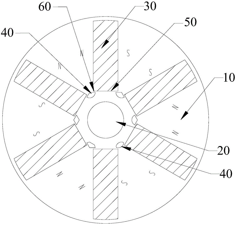
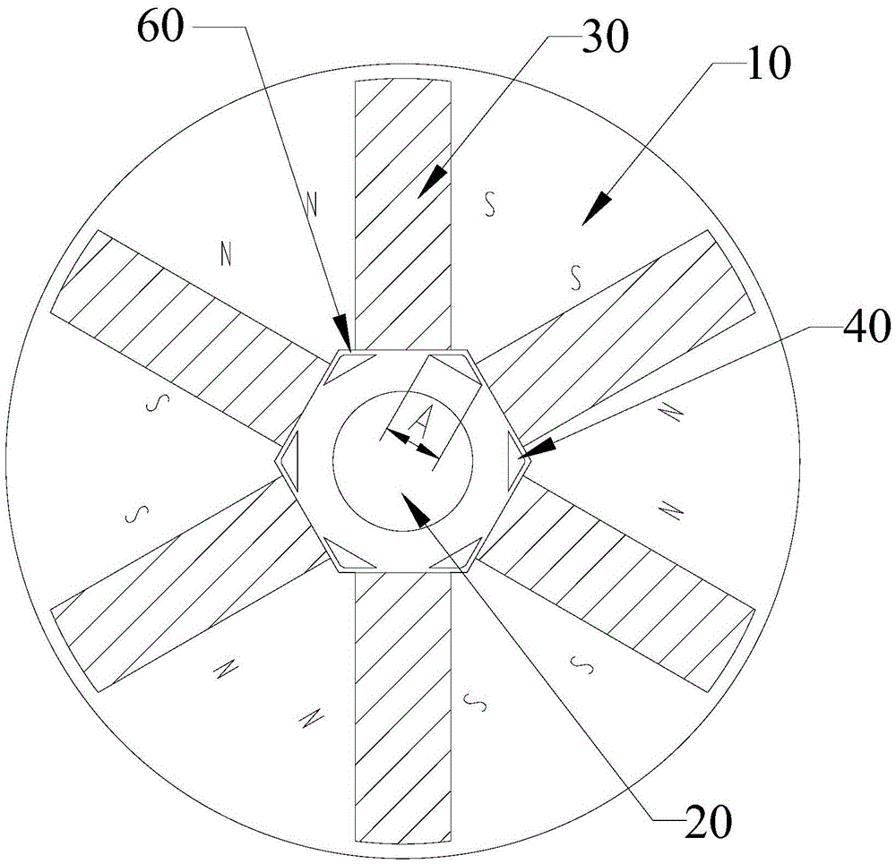
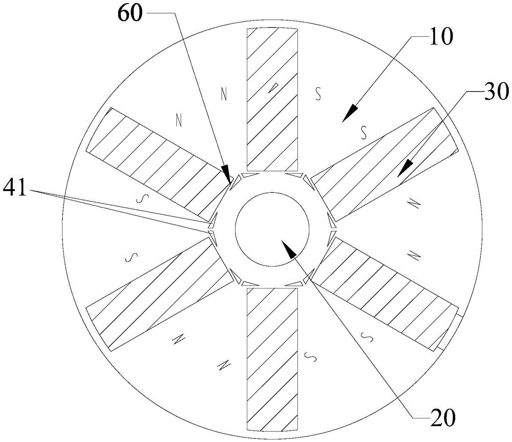
[0023] see figure 1 As shown, the first embodiment of the permanent magnet rotor of the present invention is provided, which is used in a permanent magnet motor. A tangentially magnetized permanent magnet structure is used in the permanent magnet motor. The permanent magnet rotor includes a rotor core 10 and a rotor core 10 in the middle The rotating shaft 20 of the rotor core 10 is provided with a plurality of mounting grooves 50 distributed radially along the rotor core 10, and a permanent magnet 30 is installed in each mounting groove 50, and the rotor core 10 is connected between the rotating shaft 20 and the permanent magnet A plurality of magnetic isolation slots 40 are provided in the area between 30, and each magnetic isolation slot 40 is located between two adjacent permanent ...


PUM


Abstract

The invention discloses a permanent magnet rotor and a permanent magnet motor. The permanent magnet rotor comprises a rotor core and a rotating shaft positioned in middle of the rotor core, wherein multiple mounting grooves distributed in a radial direction of the rotor core are formed in the rotor core; a permanent magnet is mounted in each mounting groove; multiple flux-insulation grooves are formed in the regions, between the rotating shaft and the corresponding permanent magnets, of the rotor core; each flux-insulation groove is formed between two adjacent permanent magnets; and flue-insulation bridges are formed in the parts, between the corresponding flux-insulation grooves and the corresponding groove bottoms, close to the rotating shaft, of the adjacent mounting grooves, of the rotor core. The problems of degradation of motor performance, excitation loss of the permanent magnets and impossibility of motor operation caused by the reason that the parts, close to the rotating shaft, of the permanent magnets cannot be fully magnetized to reach a saturated state in the prior art are effectively solved by the permanent magnet rotor and the permanent magnet motor.

Description

technical field [0001] The invention relates to the technical field of motors, in particular to a permanent magnet rotor and a permanent magnet motor. Background technique [0002] The permanent magnet motor (tangentially magnetized permanent magnet structure) in the prior art can produce a higher air gap magnetic density due to the "magnetization" effect, so that the motor has a larger torque / current ratio and torque / volume In contrast, permanent magnet motors are increasingly used in servo systems, electric traction, office automation, household appliances and other occasions. [0003] However, in the prior art permanent magnet motor (tangentially magnetized permanent magnet structure), the permanent magnets of the permanent magnet rotor are radially arranged, and one end of the permanent magnet is close to the rotating shaft (one end is deeply buried inside the rotor), and an external magnetic field is applied to the rotor. In general, when magnetizing the permanent magn...

Claims


Application Information

Patent Timeline
Patent Type & Authority Applications(China)
IPC IPC(8): H02K1/27
CPCH02K1/27H02K1/2773
Inventor 肖勇黄辉胡余生陈彬王晶
Owner ZHUHAI GREE REFRIGERATION TECH CENT OF ENERGY SAVING & ENVIRONMENTAL PROTECTION
Why Eureka
Try Eureka