Compressor and a driving method thereof

a compression and driving method technology, applied in the direction of electronic commutators, motor/generator/converter stoppers, dynamo-electric converter control, etc., can solve the problems of reducing the efficiency of the motor, generating overcurrent, and not being able to detect the position of the rotator, so as to prevent overcurren

Inactive Publication Date: 2007-04-19
SAMSUNG ELECTRONICS CO LTD
View PDF11 Cites 7 Cited by
  • Summary
  • Abstract
  • Description
  • Claims
  • Application Information

AI Technical Summary

Benefits of technology

[0016] According to an aspect of the invention, the forcibly aligning the rotator includes moving the rotator between the phase-magnetization modes toward the top dead center from the bottom dead center to prevent overcurrent and to align the rotator, accurately.

Problems solved by technology

However, since the counter electromotive force is proportional to a rotation speed of the rotator, it can not be used to detect the position of the rotator when the rotator stops or rotates at a low speed.
Although the rotator is forced to be aligned initially, when the current is applied to the winding of the motor without accurate information on the position of the rotator, overcurrent may be generated when the position of the rotator is not correct.
Such overcurrent generation lowers the efficiency of the motor.
In addition, since the rotator is forced to be aligned without accurate information on the position of the rotator, when the motor is started in a condition where any pressure exists in the motor, a large amount of current must be supplied to the motor for a long time and a start failure rate increases.

Method used


Image

  • Compressor and a driving method thereof
  • Compressor and a driving method thereof
  • Compressor and a driving method thereof

Examples


Embodiment Construction

[0029] Reference will now be made in detail to the embodiments of the present invention, examples of which are illustrated in the accompanying drawings, wherein like reference numerals refer to the like elements throughout. The embodiments are described below to explain the present invention by referring to the figures.

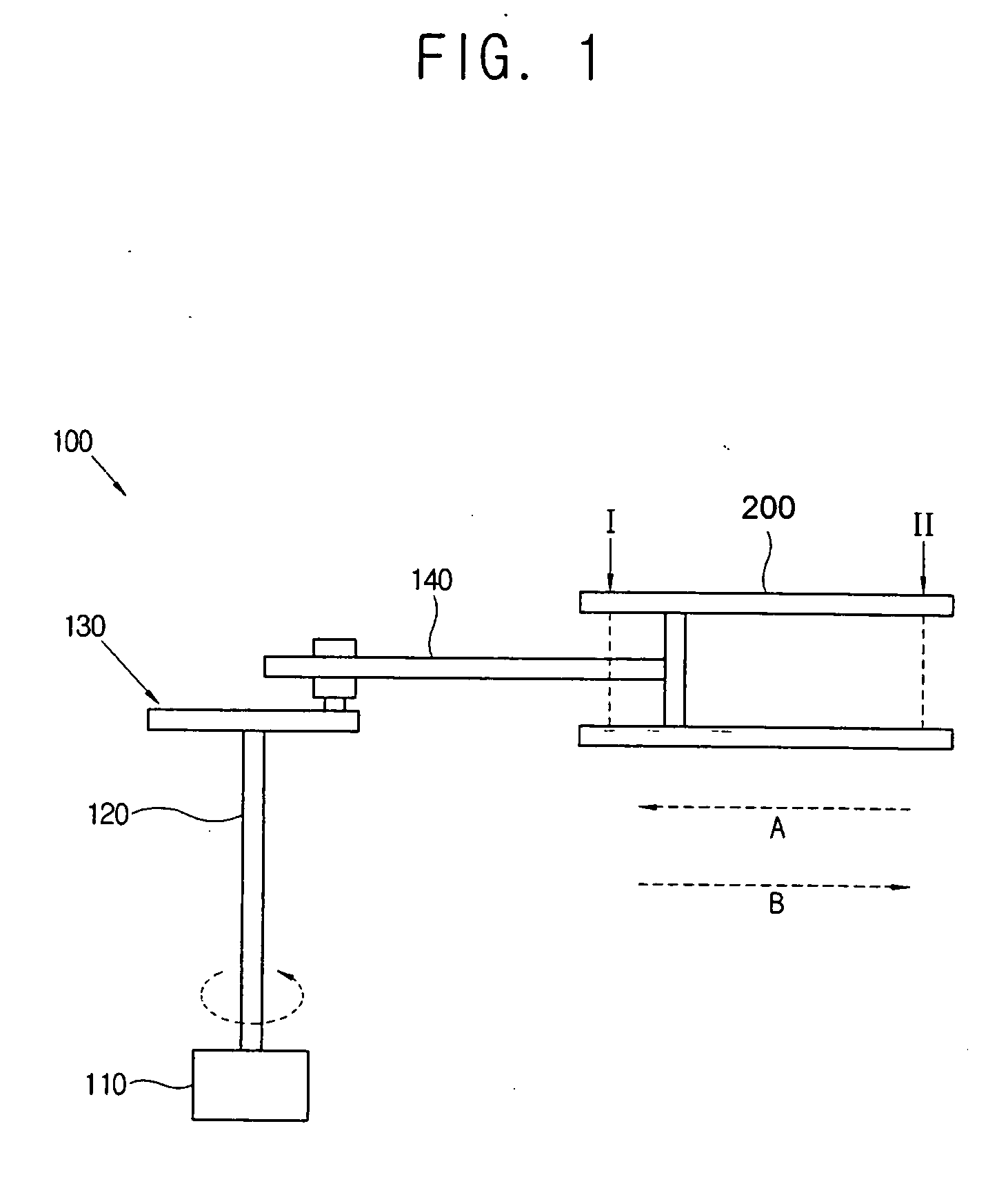
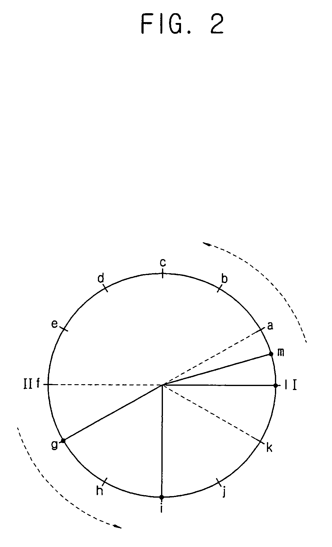
[0030]FIG. 1 is a schematic view illustrating a compressor according to the first embodiment of the present invention, and FIG. 2 is a diagram illustrating a movement of a rotator in order to explain a driving method of the compressor.

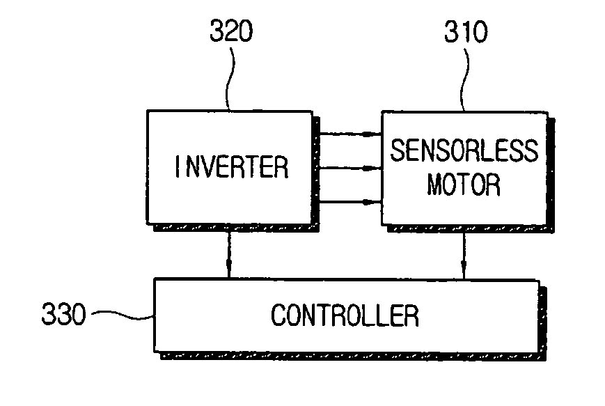
[0031] As shown in FIG. 1, the compressor comprises a sensorless motor 100 and a piston 200 connected with the sensorless motor 100 via a connecting bar 140. The compressor further comprises an inverter to supply current of three phases to the sensorless motor 100 and a controller to control the overall operation of the sensorless motor 100 (see FIG. 3).

[0032] The sensorless motor 100 comprises a rotator 110 (for example, a rotor) to ...


PUM


Abstract

A compressor having a sensorless motor and a driving method thereof. The compressor includes a sensorless motor having a rotation shaft connected to a rotator, a piston for performing a compression stroke and an intake stroke between a top dead center and a bottom dead center thereof, and a crank connecting the rotation shaft to the piston. The method includes forcibly aligning the rotator such that the rotator is positioned at a start position in the intake stroke of the piston, and accelerating rotation of the forcibly aligned rotator.

Description

CROSS-REFERENCE TO RELATED APPLICATIONS [0001] This application claims priority from Korean Patent Application No. 10-2005-0097081, filed on Oct. 14, 2005, in the Korean Intellectual Property Office, the disclosure of which is incorporated herein by reference. BACKGROUND OF THE INVENTION [0002] 1. Field of the Invention [0003] The present invention relates to a compressor and a driving method thereof. More particularly, to a compressor including a sensorless motor and a driving method of the compressor. [0004] 2. Description of the Related Art [0005] A conventional brushless direct current (BLDC) motor, used in a compressor, is a motor driven through switching by an electronic circuit using transistors, particularly metal oxide silicon field effect transistors (MOSFETs), instead of a brush and a commutator, which are important parts of a direct current (DC) motor. This type of motor operates to distribute current, which is supplied from a DC power supply, to a three or four-phase wi...

Claims


Application Information

Patent Timeline
Patent Type & Authority Applications(United States)
IPC IPC(8): H02P1/00F04B49/02H02P6/06H02P6/08H02P6/18H02P6/182H02P6/28
CPCF04B35/04F04B49/02F04B2201/0201F04B2201/0207F04B2201/0209F04B2203/0201F05B2210/12F05B2260/60Y10S417/00
Inventor CHOI, HYEN-YOUNGLEE, KWANG-WOON
Owner SAMSUNG ELECTRONICS CO LTD
Why Eureka
Try Eureka