Mobile phone antenna integrated with battery

a mobile phone antenna and battery technology, applied in the direction of antenna equipment with additional functions, slot antennas, electrical apparatus, etc., can solve the problems of limited miniaturization of mobile phone components, electronic circuits, and non-uniform density of electromagnetic waves propagating omni-directionally

Inactive Publication Date: 2009-10-15
BURY
View PDF12 Cites 16 Cited by
  • Summary
  • Abstract
  • Description
  • Claims
  • Application Information

AI Technical Summary

Benefits of technology

[0008]One objective of this invention is to provide a mobile phone antenna, comprising mobile phone battery electrodes, which ensures wide circular pattern of the electromagnetic wave generated by the antenna.

Problems solved by technology

However, miniaturization of mobile phone components is limited by technological constraints.
A major problem of such an antenna is the need to use electronic circuits to connect the antenna to a transmitter or receiver of a mobile phone.
Another major problem is a non-uniform density of the electromagnetic waves propagating omni-directionally.

Method used


Image

  • Mobile phone antenna integrated with battery
  • Mobile phone antenna integrated with battery
  • Mobile phone antenna integrated with battery

Examples


Embodiment Construction

[0030]Detailed description will be given below with reference to accompanying drawings.

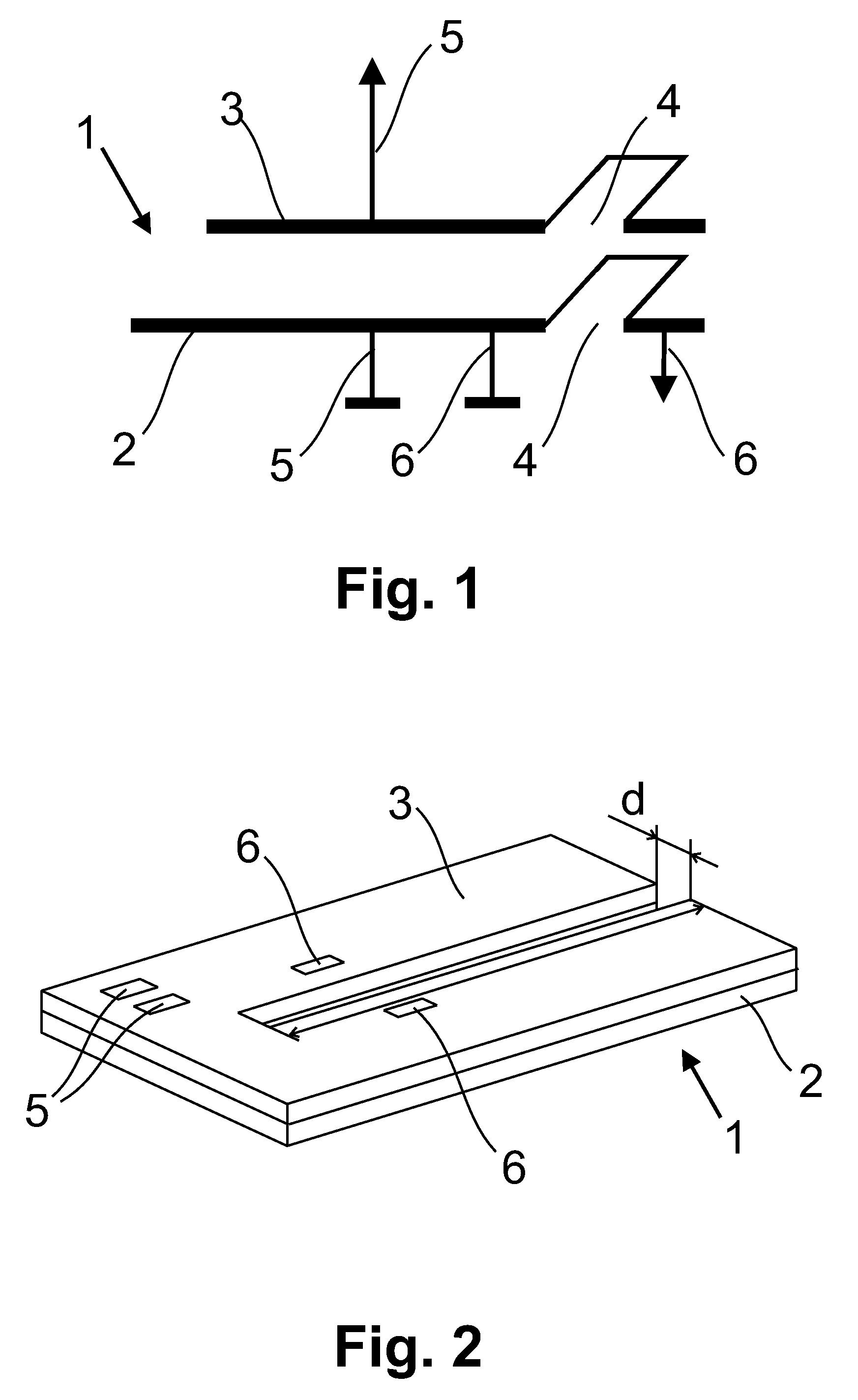
[0031]FIG. 1 shows an electric circuit schematic of the battery 1, comprising two electrodes 2 and 3 of opposite polarity, provided with a slot 4, forming the antenna. The electrode 2 is provided with antenna contacts 6, located on both sides of the slot 4 and both electrodes 2 and 3 of the battery 1 are provided with battery contacts 5.

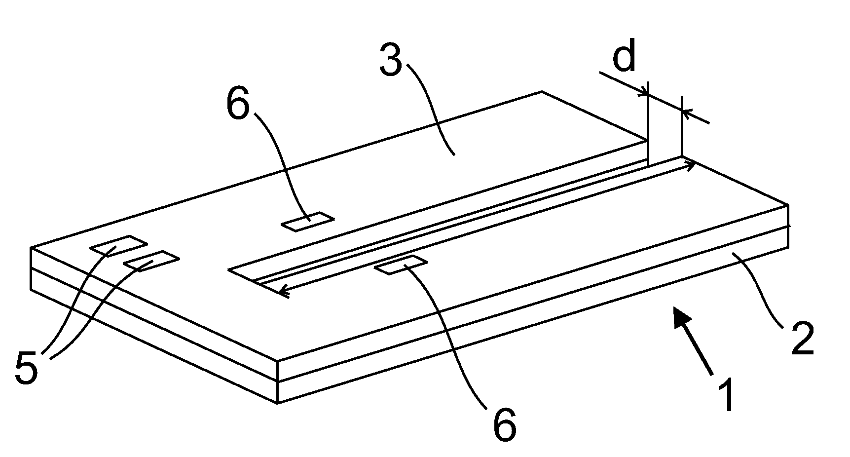
[0032]FIG. 2 is a perspective view of a mobile phone antenna, comprising a slot 4 made in both electrodes 2 and 3 of the mobile phone battery 1 and dielectric layer 7 separating these electrodes. The antenna depicted in FIG. 2 has a slot 4, the axis of which is a straight line and which is open at one side. The walls of the slot 4 are parallel to each other. FIG. 2 shows also, an example of a layout of the battery contacts 5 and the antenna contacts 6.

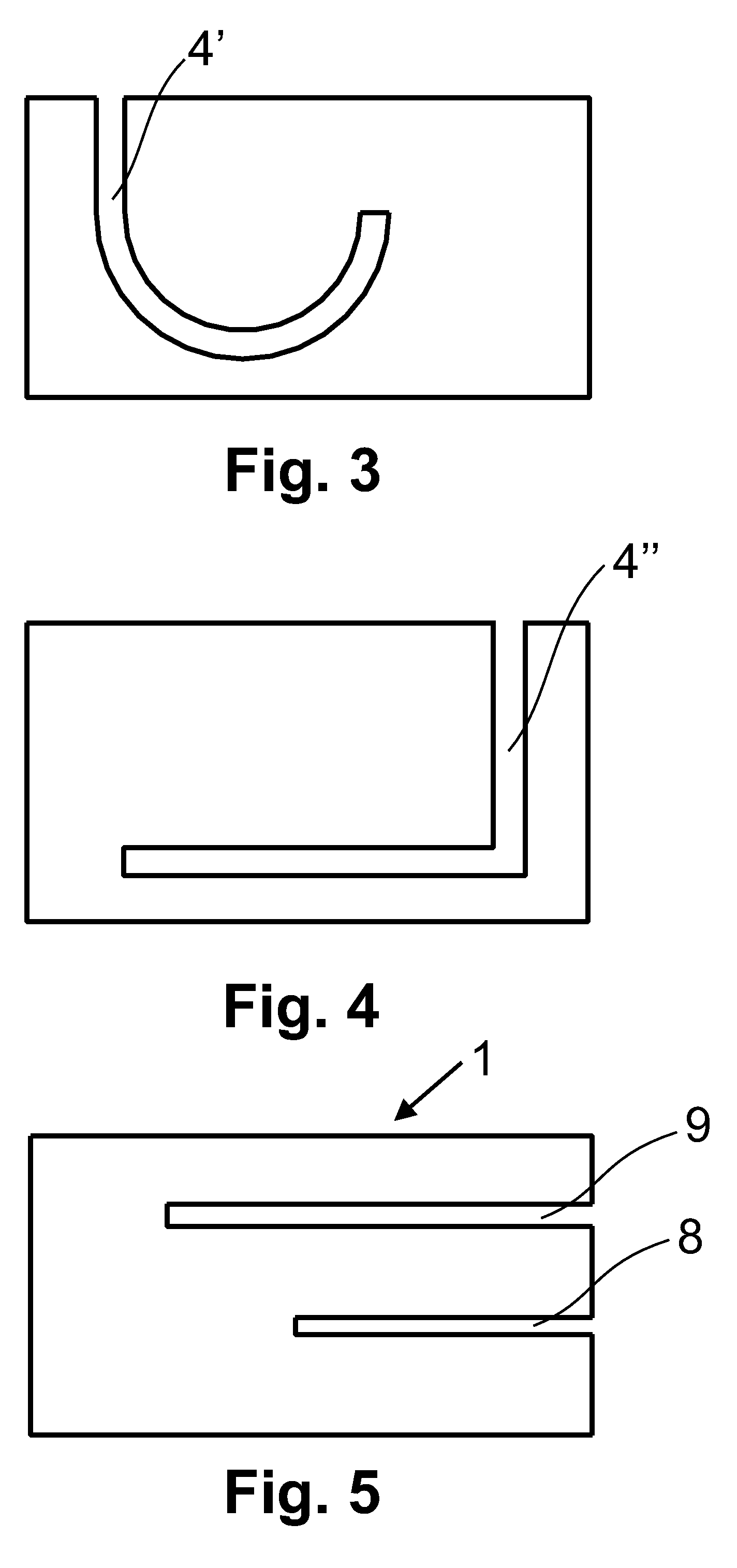
[0033]FIG. 3 is a top plan view of the antenna in which the gap 4′ has a curved-line axis, whereas FIG. 4 is a top ...


PUM

PropertyMeasurementUnit
dielectricaaaaaaaaaa
widthaaaaaaaaaa
lengthaaaaaaaaaa

Abstract

A mobile phone antenna integrated with a battery, comprising: a plurality of battery electrodes; a dielectric layer separating the battery electrodes from one another; and a slot formed in the battery electrodes; wherein walls of the slot are parallel to each other and the electrodes with said slot are adapted to emit and receive electromagnetic waves.

Description

CROSS-REFERENCE TO RELATED APPLICATIONS[0001]Pursuant to 35 U.S.C. §119 and the Paris Convention Treaty, this application claims the benefit of European Patent Application No. EP08460011 filed Apr. 9, 2008, the contents of which are incorporated herein by reference in their entirety.BACKGROUND OF THE INVENTION[0002]1. Field of the Invention[0003]This invention relates to a mobile phone antenna integrated with a battery.[0004]2. Description of the Related Art[0005]In recent decades, mobile phones have been subject to miniaturization. However, miniaturization of mobile phone components is limited by technological constraints. Therefore, a visible trend exists towards integration of mobile phone components so that the integrated parts occupy a smaller space within mobile phones than they would as separate parts. For example, a phone keypad has been integrated with phone display and provided in touch screen form. Similarly, resonance chambers of phone speakers have been designed in such...

Claims


Application Information

Patent Timeline
Patent Type & Authority Applications(United States)
IPC IPC(8): H01Q13/10H01M14/00
CPCH01Q1/243H01Q13/10H01Q1/44
Inventor BURY, HENRYK
Owner BURY
Why Eureka
Try Eureka