
Bi-phasic bioretention system
a bioretention system and biphasic technology, applied in the direction of sewage draining, filtration separation, separation process, etc., can solve the problems of chemical pollution to the environment and to humans, and achieve the effect of optimizing the retention time of runoff, facilitating biological degradation of many organic pollutants, and effective treatmen
- Summary
- Abstract
- Description
- Claims
- Application Information
AI Technical Summary
Benefits of technology
Problems solved by technology
Method used
Image

Examples
Embodiment Construction
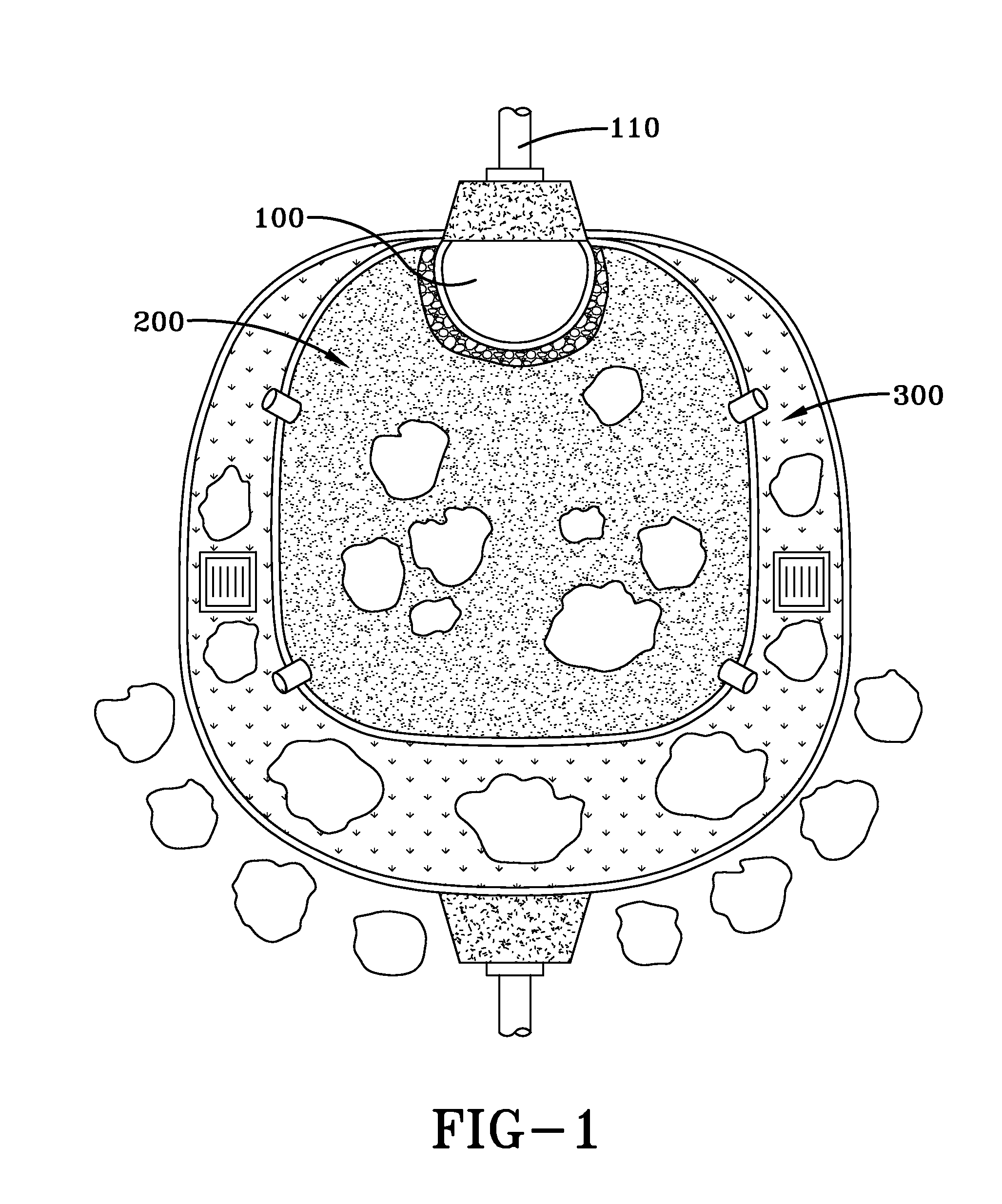
[0015]Exemplary embodiments incorporate a sequence from anaerobic to aerobic conditions which enhance organic pollutant removal by microorganisms due to the fact that the bi-phasic bioretention conditions support a diversity of electron acceptors and environmental conditions, thus supporting a much wider range of degrading microorganisms. The embodiment shown in FIG. 1 includes an anaerobic zone 200, an aerobic zone 300. The size (i.e., surface area and medium depth) of each zone is determined based on the drainage area and the desired runoff volume to be caught and treated. In this embodiment, the storm-water runoff is directed to a micropooling area 100 in the anaerobic zone by an influent pipe 110.
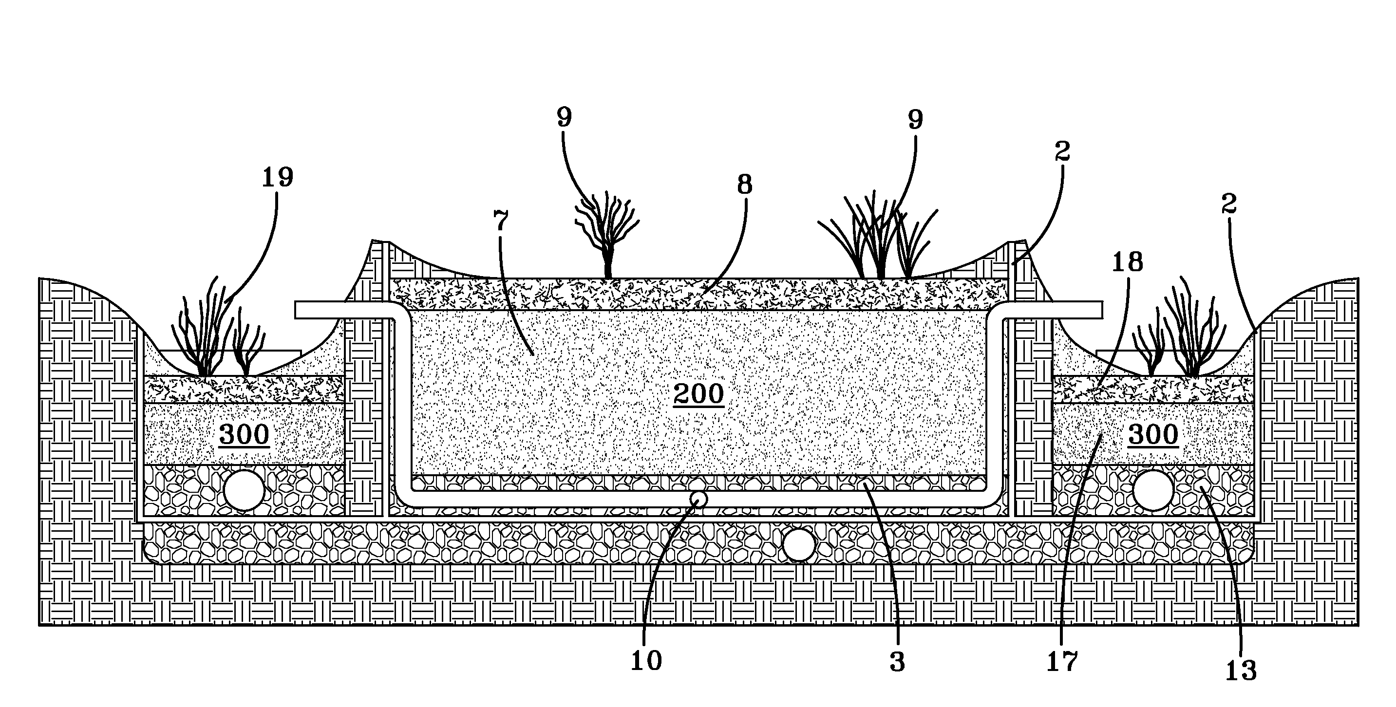
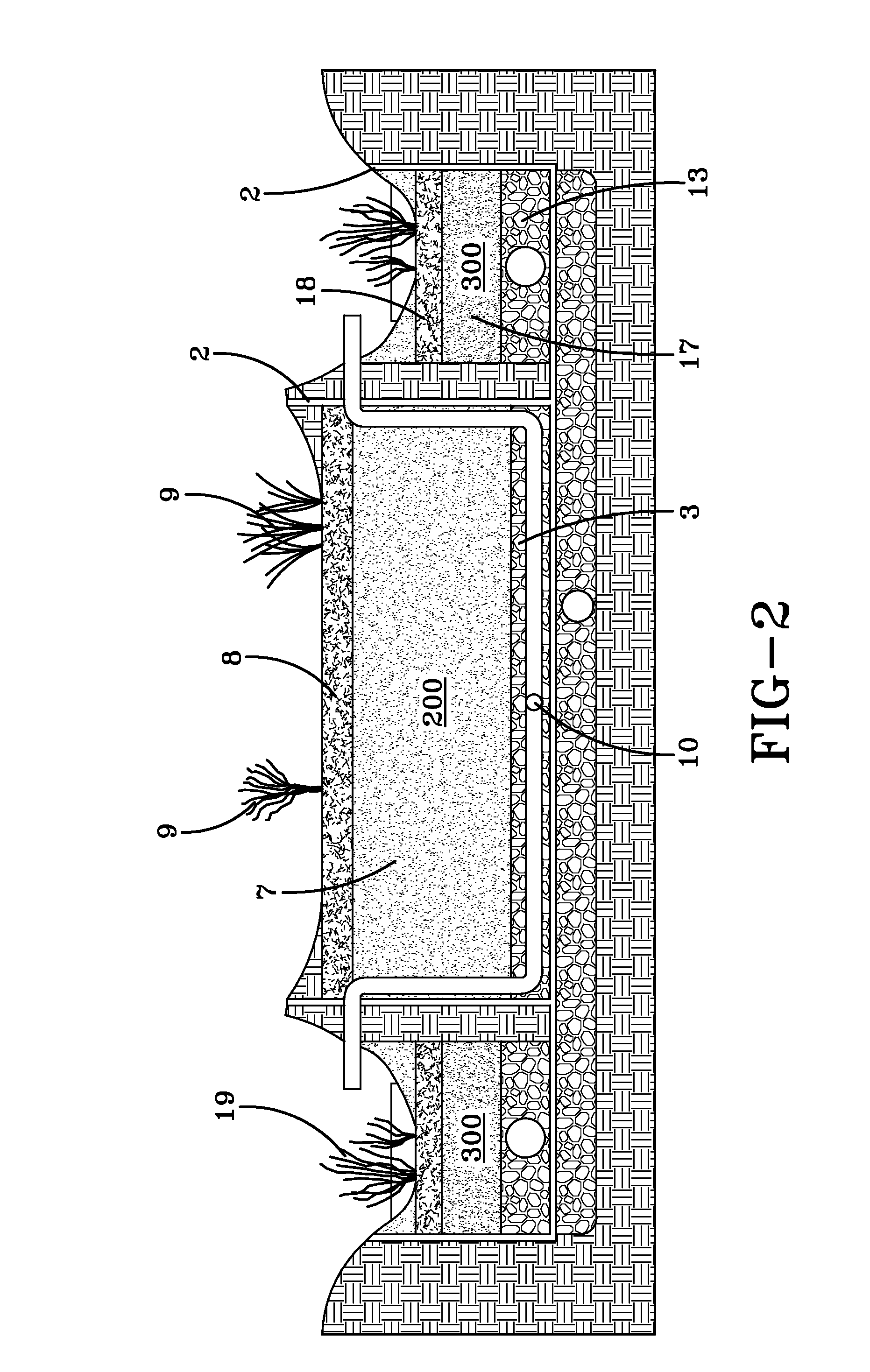
[0016]FIG. 2 further illustrates the composition of FIG. 1. In an embodiment, the anaerobic zone comprises plastic liners 2, drainage pipes (further illustrated in FIG. 3), an underdrainage layer 3, a mulch layer 8, herbaceous plants 9, and a mixture of sand, topsoil, and compost collec...
PUM
| Property | Measurement | Unit |
|---|---|---|
| impermeable | aaaaa | aaaaa |
| water impermeable | aaaaa | aaaaa |
| diameter | aaaaa | aaaaa |
Abstract
Description
Claims
Application Information