
Humeral rotating burr guide

a technology of humeral rotation and guide rod, which is applied in the field of orthopaedic surgery, can solve problems such as patient complications and possible errors

Active Publication Date: 2009-10-22
DEPUY PROD INC
View PDF27 Cites 86 Cited by
  • Summary
  • Abstract
  • Description
  • Claims
  • Application Information

AI Technical Summary

Benefits of technology

The cutting guide facilitates reproducible and accurate bone resection in multiple planes, reducing the risk of ill-fitting prostheses and simplifying the surgical process by allowing for simultaneous removal of the humeral greater tubercle, thereby improving surgical efficiency and patient outcomes.

Problems solved by technology

The possibility for error exists with this free hand approach.
Inaccurate resection can result in an ill-fitting prosthesis which may cause complications for the patient and may eventually require replacement of the prosthetic device.
However, current cutting guides only allow for the cutting of the humeral greater tubercle in one plane at a time.

Method used


Image

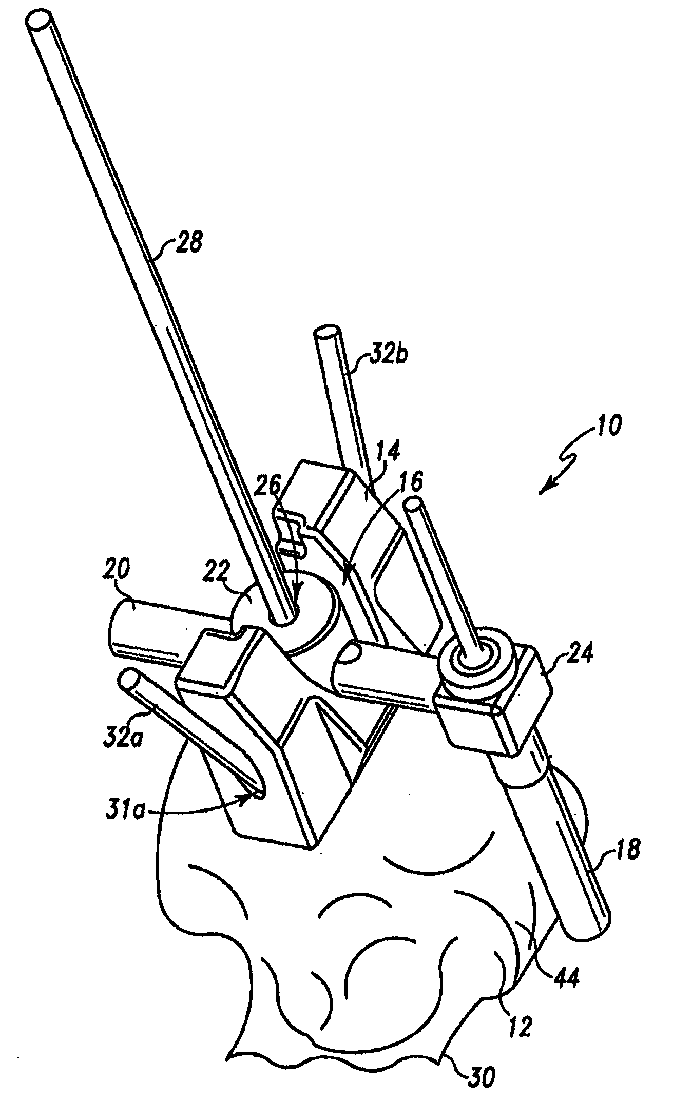
  • Humeral rotating burr guide
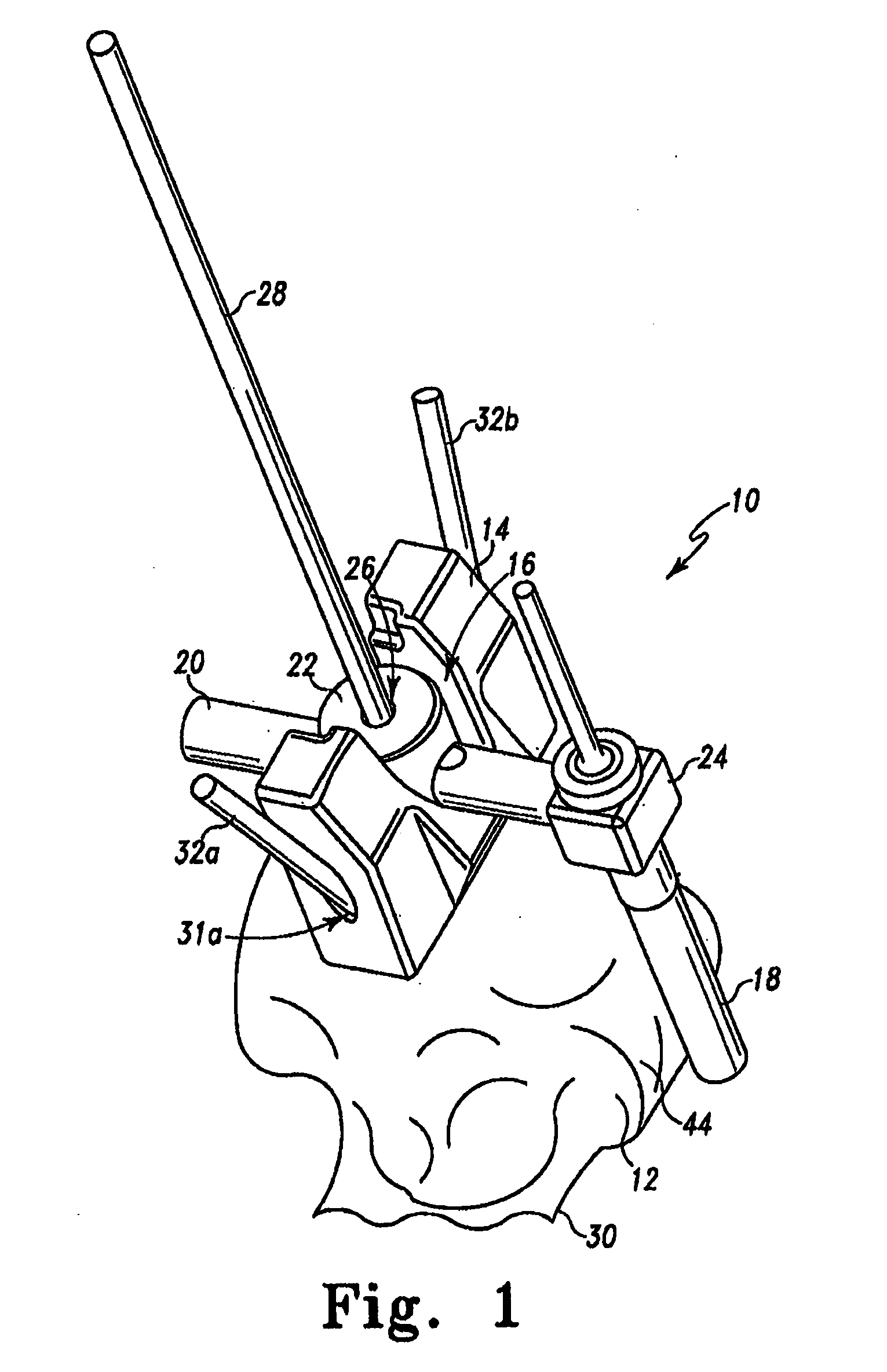
  • Humeral rotating burr guide
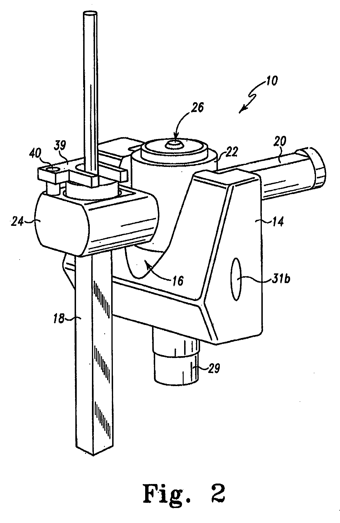
  • Humeral rotating burr guide

Examples


Embodiment Construction

[0027]Embodiments of the present invention and the advantages thereof are best understood by referring to the following descriptions and drawings, wherein like numerals are used for like and corresponding parts of the drawings.

[0028]For the purposes of promoting an understanding of the principles of the invention, reference will now be made to the embodiments illustrated in the drawings and described in the following written specification. It is understood that no limitation to the scope of the invention is thereby intended. It is further understood that the present invention includes any alterations and modifications to the illustrated embodiments and includes further applications of the principles of the invention as would normally occur to one skilled in the art to which this invention pertains.

[0029]Referring now to FIGS. 1 and 2, a cutting guide 10 is provided that allows for the cutting of a humeral head 12. The cutting guide 10 is used to remove a portion of the humeral head ...


PUM


Abstract

A bone cutting assembly includes a guide pin that may be securely inserted into a bone to define a cutting axis. The bone cutting assembly also includes a housing having a cam surface and features for temporarily fastening the housing to the bone. The bone cutting assembly also includes a burr mounting arm that rotatably and slidably fits onto the guide pin so that the arm can swing around the cutting axis and also translate up and down the guide pin. A user may move the burr mounting arm about the cutting axis so that the arm follows along the cam surface of the housing.

Description

RELATED APPLICATIONS[0001]This specification is a continuation-in-part of U.S. patent application Ser. No. 12 / 062,952 of the same title, filed on Apr. 4, 2008 and herein incorporated by reference in its entirety.TECHNICAL FIELD OF THE INVENTION[0002]The devices and methods disclosed herein relate generally to the field of orthopaedics, and more particularly, to surgical arthroplasty.BACKGROUND OF THE INVENTION[0003]Patients who suffer from the pain and immobility caused by osteoarthritis and rheumatoid arthritis have an option of joint replacement surgery. Joint replacement surgery is quite common and enables many individuals to function properly when it would not be otherwise possible to do so. Artificial joints are usually comprised of metal, ceramic and / or plastic components that are fixed to existing bone.[0004]One type of joint replacement surgery is shoulder arthroplasty. During shoulder arthroplasty, the humeral head must be resected to allow for the insertion of a humeral st...

Claims


Application Information

Patent Timeline
Patent Type & Authority Applications(United States)
IPC IPC(8): A61B17/56
CPCA61B17/1684A61B17/1739A61B2017/1778A61B2017/1602A61B17/1778
Inventor LONG, JACK F.DONNELLY, STEPHEN R.
Owner DEPUY PROD INC
Learn More