Optical Disk Player Capable of Monitoring the Optical Disk Status

a technology of optical disk player and which is applied in the direction of information storage, instruments, data recording, etc., to achieve the effect of reducing the width of the shell of the optical disk player reducing the distance at the optical disk transport direction, and reducing the width of the optical disk player shell at the optical disk insertion direction

Active Publication Date: 2009-11-12
GULIN ELECTRICAL EQUIP CO LTD SHENZHEN
View PDF5 Cites 4 Cited by
  • Summary
  • Abstract
  • Description
  • Claims
  • Application Information

AI Technical Summary

Benefits of technology

[0011]For the support part and the trigger bar of the optical disk loading final position detection mechanism both adopt rotatable way to be connected, the displacement distance at the optical disk transport direction is effectively reduced, so as to reduce the width of the shell of the optical disk player at the optical disk insertion direction. At the same time, for the detection parts of the guiding mechanism are located between the plummer and the delivery roll, the width of the shell of the optical disk player at the optical disk insertion direction can be further reduced. So, it is ensured that the width of the shell of the optical disk player of the present invention can be made as 80-90 millimeters wide at the optical disk insertion direction.

Problems solved by technology

Especially for that kind of optical disk players which transports the optical disk to the playing position via a delivery roll, for the internal structure is complicated, the shell of the optical disk player can not be made less than the outer diameter of the optical disk.

Method used


Image

  • Optical Disk Player Capable of Monitoring the Optical Disk Status
  • Optical Disk Player Capable of Monitoring the Optical Disk Status
  • Optical Disk Player Capable of Monitoring the Optical Disk Status

Examples


Embodiment Construction

[0024]Aspects of the present invention are best understood from the following detailed description when read with reference to the accompanying figures.

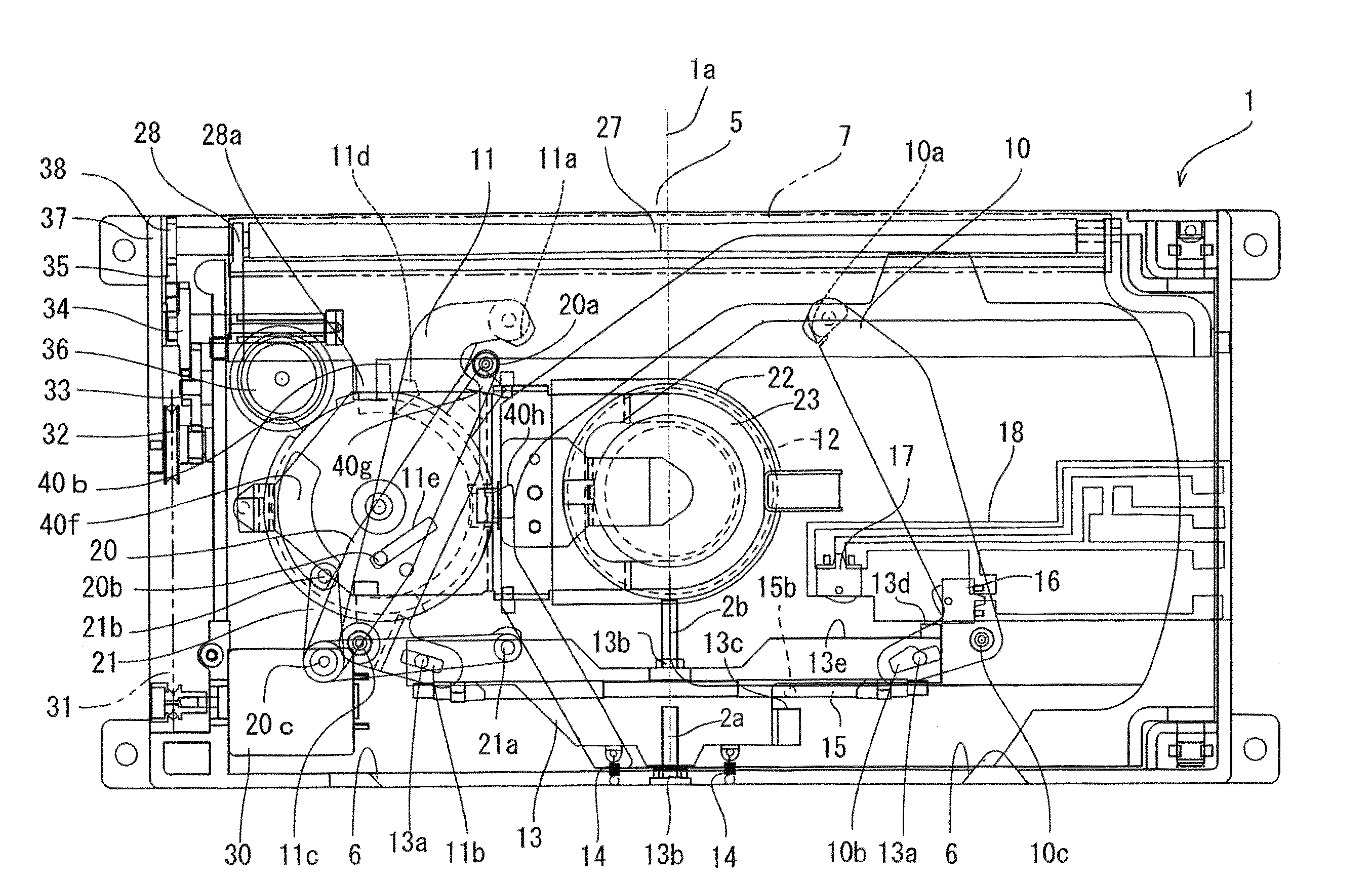
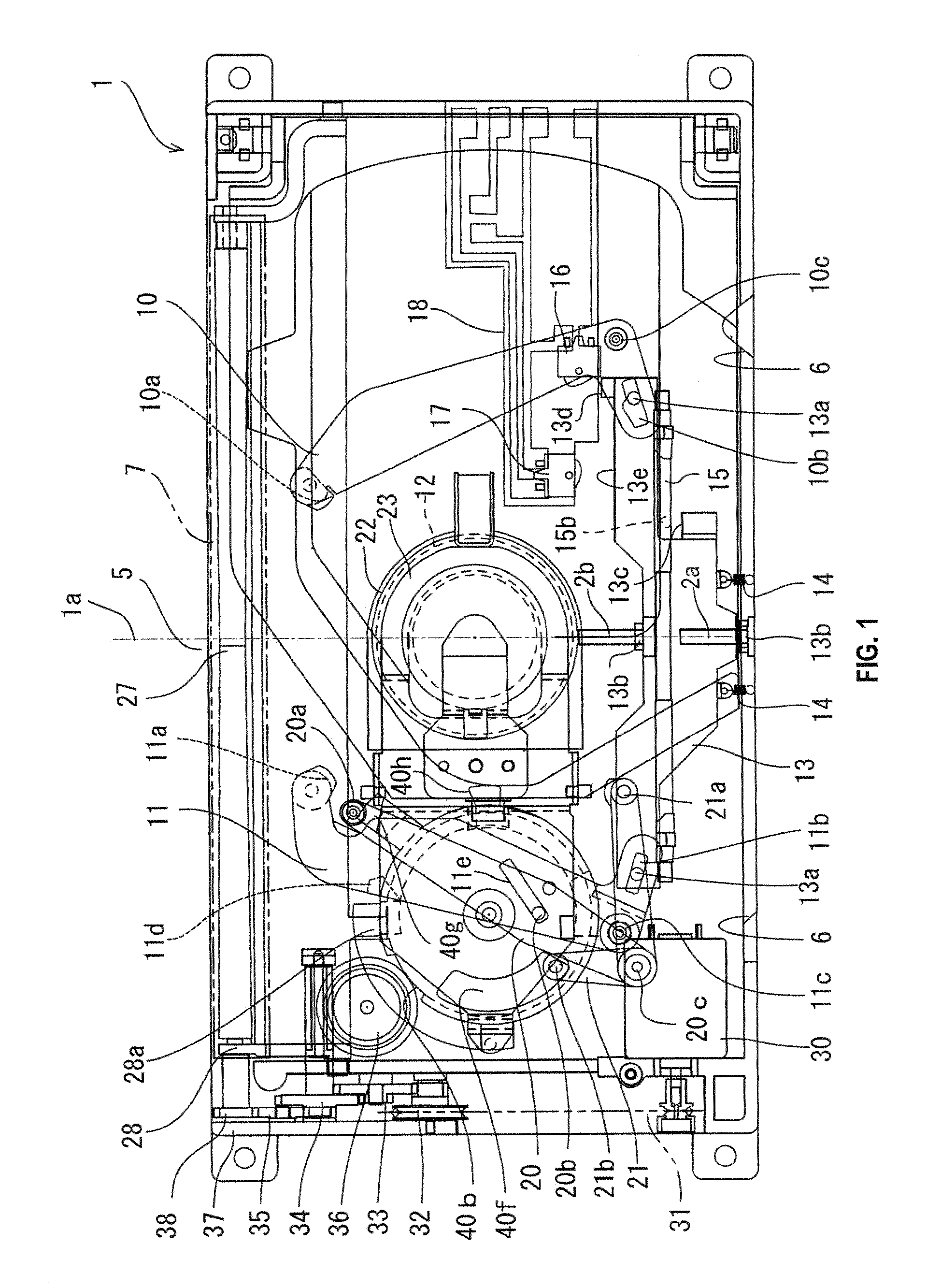
[0025]Referring to from FIG. 1 to FIG. 7, the optical disk player comprises: a shell 1, a plummer 12 fixed in the shell, a transport mechanism for transporting the optical disk between the optical disk insertion inlet 5 and the plummer 12, a guiding mechanism for guiding the optical disk to the center of the transport path, an optical disk loading final position detection mechanism, and a control part 40; when an optical disk is transported to be above the plummer 12, the control part 40 controls a chuck plate 22 to keep the optical disk on the plummer 12, and controls the transport mechanism to cancel holding the optical disk.

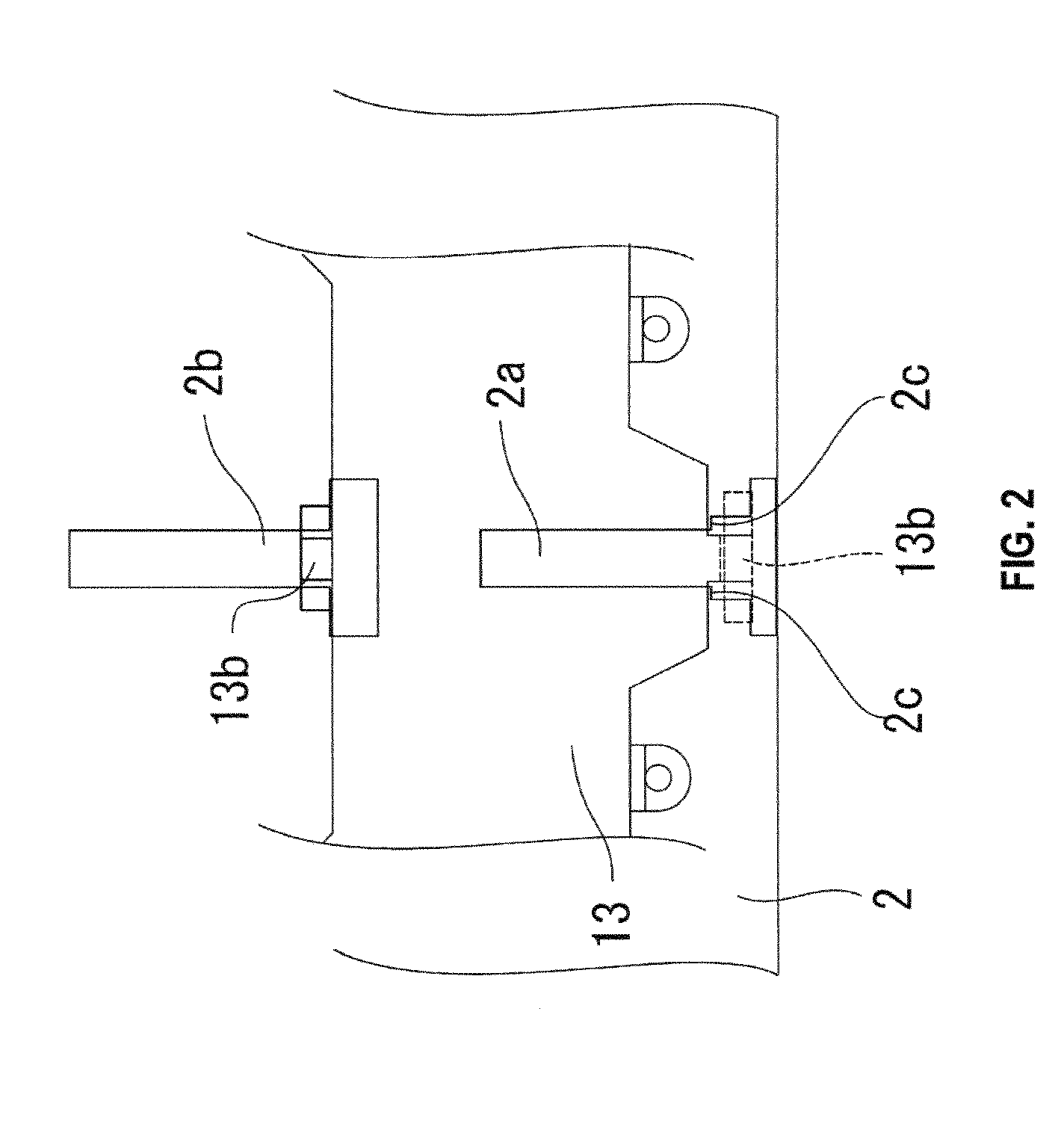
[0026]The shell 1 is composed of an upper base plate 2 and a lower base plate 3, and the upper, lower base plates are connected as one body via connecting components such as screws; a clearance 4 used as the op...


PUM

PropertyMeasurementUnit
outer diameteraaaaaaaaaa
widthaaaaaaaaaa

Abstract

An optical disk player, which comprises: a shell, a plummer fixed in the shell, an optical disk transport mechanism, a guiding mechanism, an optical disk loading final position detection mechanism, and a control part; the shell is 80-90 millimeters wide at the optical disk insertion direction; the detection parts of the guiding mechanism are located between the plummer and the delivery roll of the transport mechanism; the optical disk loading final position detection mechanism comprises a support part and a trigger bar; one end of the support part is rotatablely fixed to the upper base plate near the detection part of one detection bar, and its middle is provided with an assorted part interacting with the detection bar; the middle of the trigger bar is rotatablely fixed to the free end of the support part, of which one end is provided with a contact part for contacting the periphery of an optical disk, and the other end is connected to the control part. When an optical disk is at the playing position, a part of the optical disk will be exposed out of the shell of the optical disk player, so, when the optical disk is played, the status of the optical disk in the optical disk player can be intuitively seen from the outside.

Description

BACKGROUND OF THE INVENTION[0001]1. Field of the Invention[0002]The present invention involves an optical disk player especially involves an optical disk player that transports the optical disk inserted from the insertion inlet to the playing position via a delivery roll.[0003]2. Description of the Related Art[0004]In an existing optical disk player, when the optical disk gets to the playing position, the whole optical disk is entirely contained in the player, and the status of the optical disk being played can not be seen from the outside. Especially for that kind of optical disk players which transports the optical disk to the playing position via a delivery roll, for the internal structure is complicated, the shell of the optical disk player can not be made less than the outer diameter of the optical disk. For example, a Japanese patent application with the publication number of 2008-135106 (P2008-135106A) disclosed such an optical disk playing device.SUMMARY OF THE INVENTION[000...

Claims


Application Information

Patent Timeline
Patent Type & Authority Applications(United States)
IPC IPC(8): G11B17/04
CPCG11B17/0515G11B17/051
Inventor CHEN, YUNG TA
Owner GULIN ELECTRICAL EQUIP CO LTD SHENZHEN
Why Eureka
Try Eureka