Junction box cover assembly

a box cover and assembly technology, applied in the direction of casings/cabinets/drawers, casings/cabinets/drawers details, electrical equipment, etc., can solve the problems of assembly not allowing the flush mounting of electrical components, mounting plates protruding from the surface of the wall, and no standard or specification for detailing and finishing roughed

Active Publication Date: 2009-11-19
LEHR HAROLD
View PDF11 Cites 51 Cited by
  • Summary
  • Abstract
  • Description
  • Claims
  • Application Information

AI Technical Summary

Problems solved by technology

There is generally no standard or specification for detailing and finishing the roughed-out area in an architectural or aesthetically pleasing manner.
The drawback of the known lighting system assembly consists in that the facia mounting plate protrudes from the surface of the wall and is aesthetically unsightly.
In addition, the assembly does not allow an electrical component to be flush mounted without the use of a separate canopy.
Other flush mount systems of prior art workers result in surface cracking and are difficult to install.

Method used


Image

  • Junction box cover assembly
  • Junction box cover assembly
  • Junction box cover assembly

Examples


Embodiment Construction

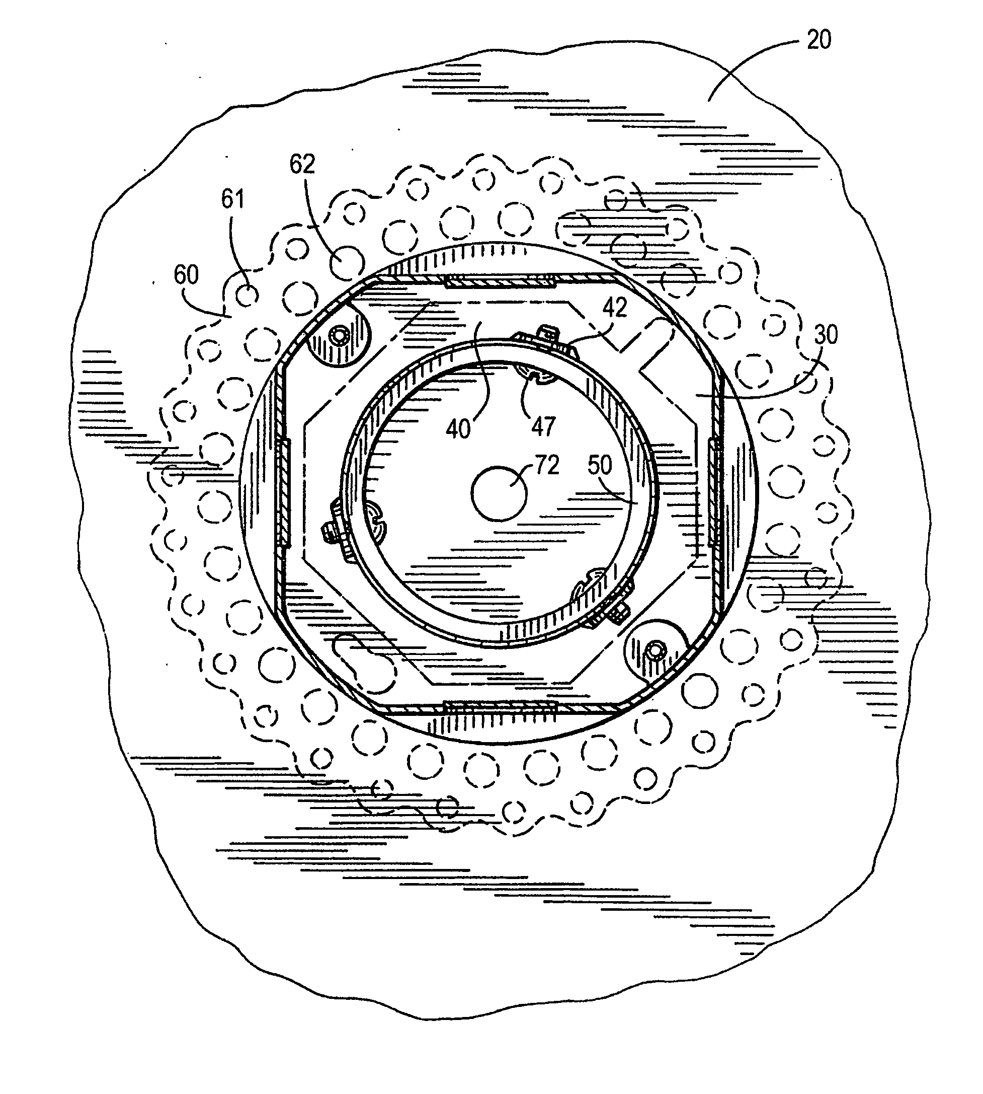
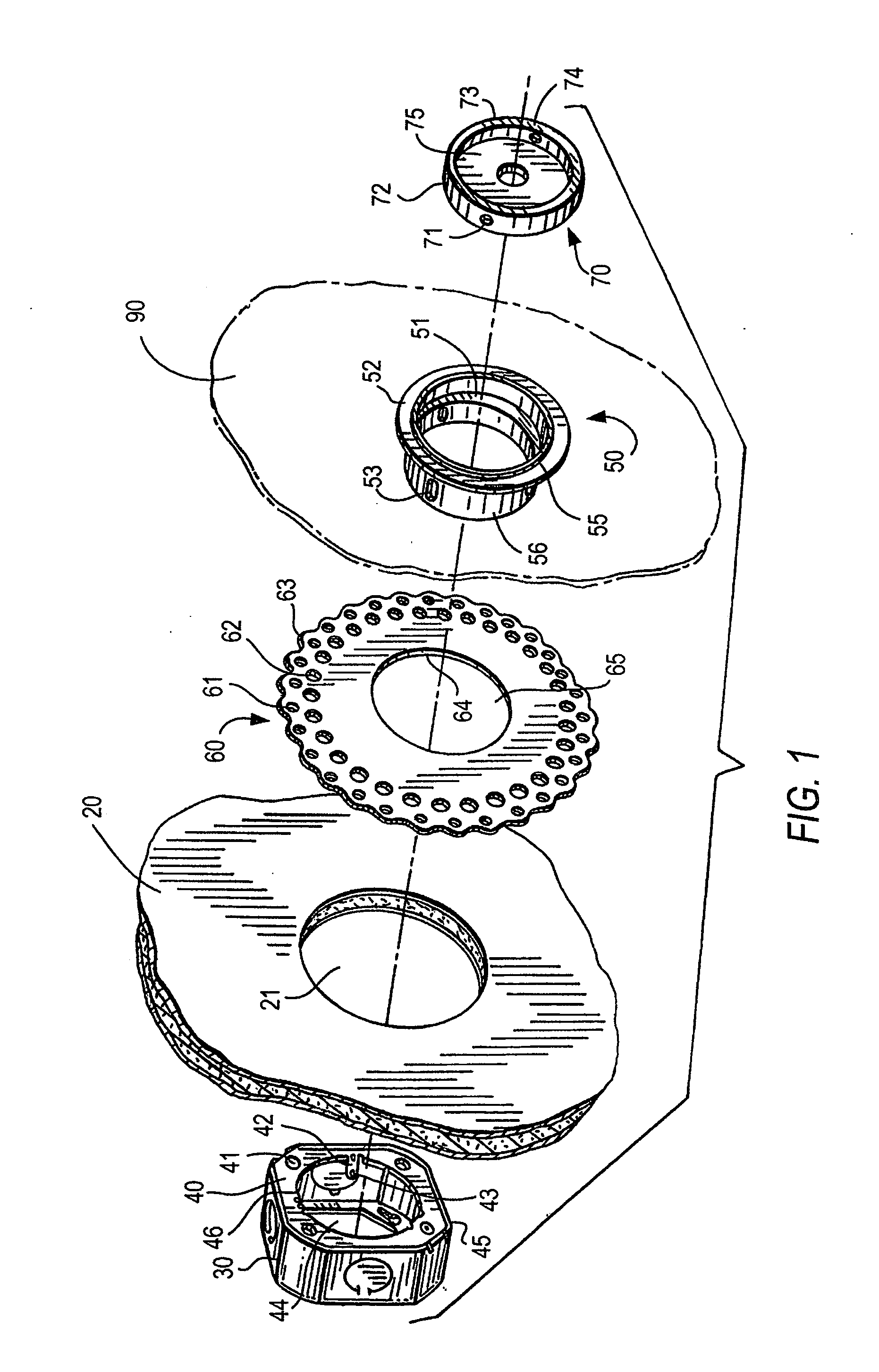
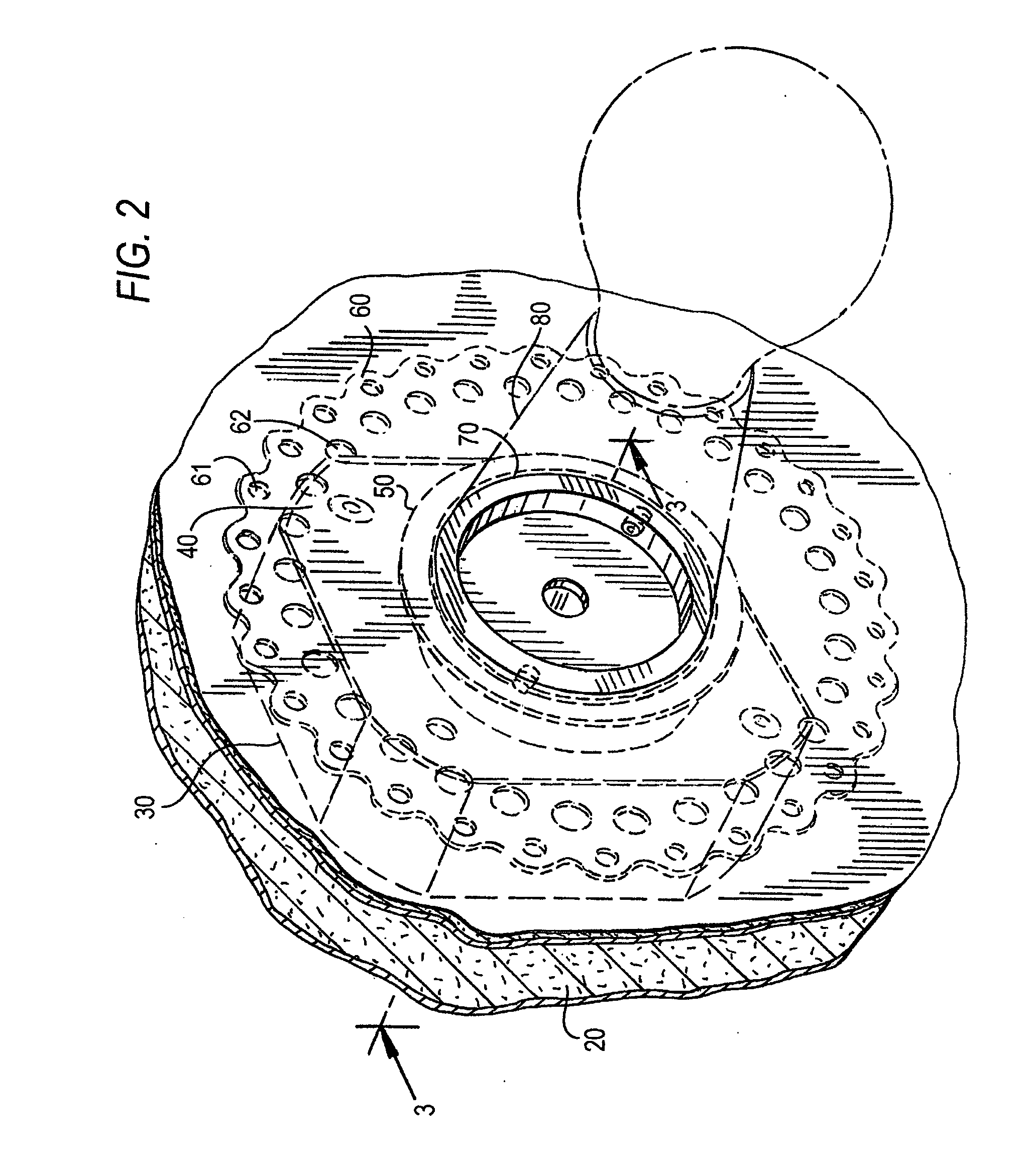
[0019]FIG. 1 illustrates an exploded perspective view of the junction box cover assembly of the present invention. The junction box cover assembly is adapted for mounting a fixture (see FIG. 2) on a wall or ceiling. As used herein, the term “fixture” means any of the following: wall lamps, pendants, surface mounted track, monopoints, communication jacks, sensors and detectors, blank-up covers, and custom box openings and mountings, fittings, and devices. As used herein, terms “wall” and “ceiling” mean a structurally supported surface, usually of a material such as gypsum board, but also can be wood, plaster, cementitious, metal, etc., that is a part of a building's construction. As described hereinbelow, the junction box cover assembly has several component parts.

[0020]An adapter plate 40 is mounted on a junction box 30. The adapter plate 40 has an opening 44 which is defined by an inner edge 46. The outer edge 45 of the adapter plate 40 preferably coincides with the size and shape ...


PUM

PropertyMeasurementUnit
adhesiveaaaaaaaaaa
areaaaaaaaaaaa
sizesaaaaaaaaaa

Abstract

A junction box cover assembly for mounting a fixture on a wall or ceiling. The assembly includes an adapter plate for being mounted on a junction box. A patch for supporting the cover assembly on the wall or ceiling in a mounted condition is provided. The patch is adapted to rest flush against the wall or ceiling and to be covered by and embedded in a joint compound. A hub having a body is insertable through openings of the patch and the adapter plate. The assembly includes elements for securing the hub to the adapter plate and elements for securing the hub to the patch. An insert is attachable to the hub for mounting a fixture or providing a blank-up cover.

Description

FIELD OF THE INVENTION[0001]The present invention relates to a junction box cover assembly for a wall or ceiling and to a method of attaching and aligning the cover assembly to a junction box while independently attaching and aligning the cover assembly to the surface of the wall or ceiling. The junction box cover assembly is used either for mounting a fixture or for providing a blank-up cover to finish the roughed-out opening surrounding the junction box.BACKGROUND OF THE INVENTION[0002]A junction box is a container for electrical junctions, usually intended to conceal them from sight and to some extent to eliminate tampering. It can be a small metal or plastic container, such as those intended to form part of wiring, especially in buildings. In this type of application, it may form part of an electrical conduit wiring system, or may be buried in the plaster of a wall, concealed behind an access panel or cast into concrete with only the lid showing. It may or may not include termin...

Claims


Application Information

Patent Timeline
Patent Type & Authority Applications(United States)
IPC IPC(8): H02G3/14B23P11/00
CPCY10T29/49826H02G3/14
Inventor LEHR, HAROLD
Owner LEHR HAROLD
Why Eureka
Try Eureka