

Windows with electrically controllable transmission and reflection
- Summary
- Abstract
- Description
- Claims
- Application Information
AI Technical Summary
Benefits of technology
Problems solved by technology
Method used
Image

Examples
first embodiment
[0051]FIGS. 3A-4B show a controllable tint optical structure, including a sandwich of an absorptive polarizing film, an active layer that changes the polarization of light in response to an external stimulus, and a reflective polarizing film acting as an analyzer, to provide polarization selective reflection of the light exiting the active layer. For light entering from the absorptive polarizer side (the front side), one polarization state of the light is absorbed and the other state is transmitted. For light entering the reflective side, one polarization state of the light is reflected and the other is transmitted into the active layer. For the case of linear polarization and with the parallel polarizer orientations in FIGS. 3A-3B, when the active layer is activated, the polarization of the light is rotated. The light entering from the absorptive polarizer side is reflected by the reflective polarizer, which subsequently transmits through the absorptive polarizer. In such case, thi...
second embodiment
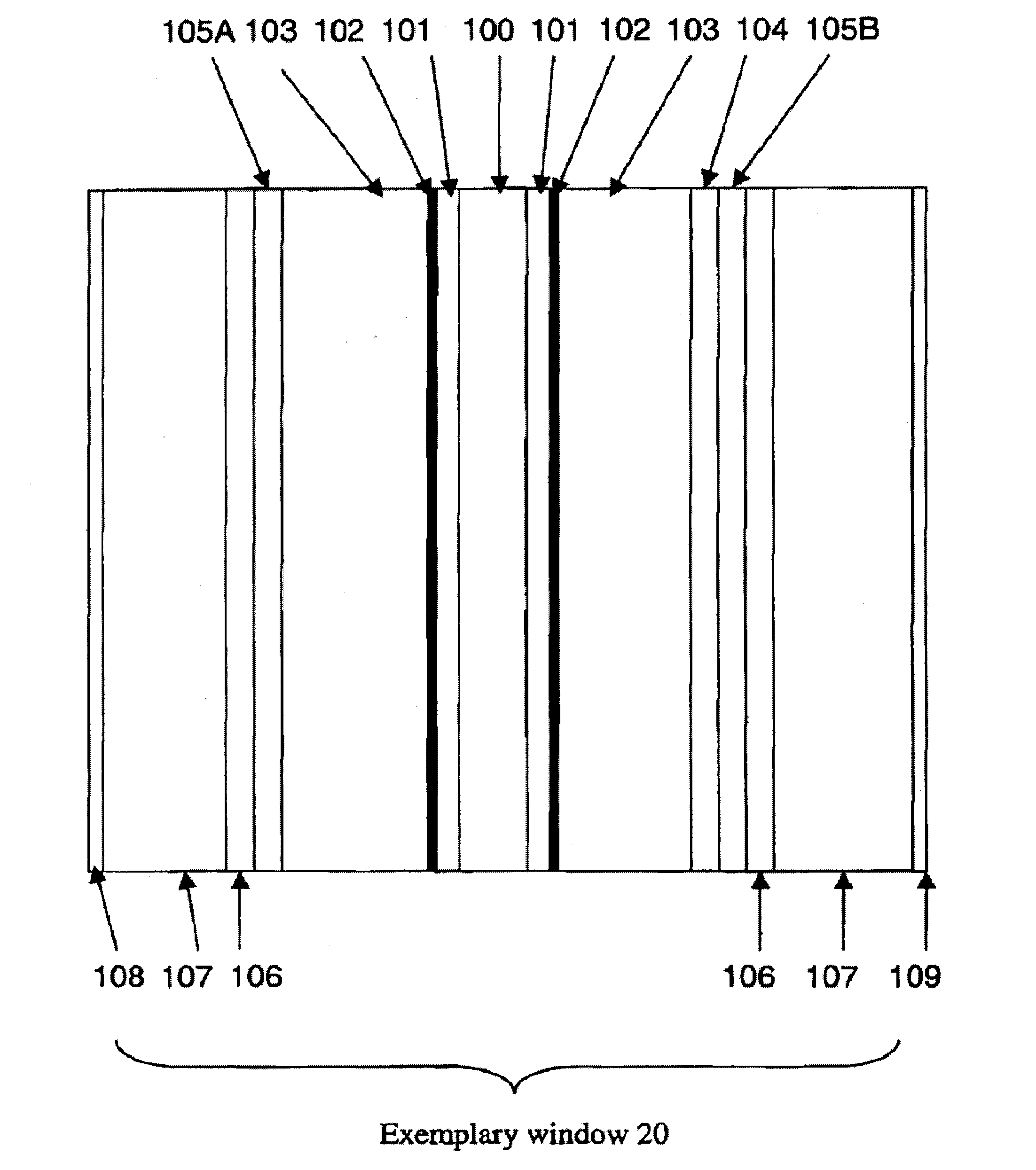
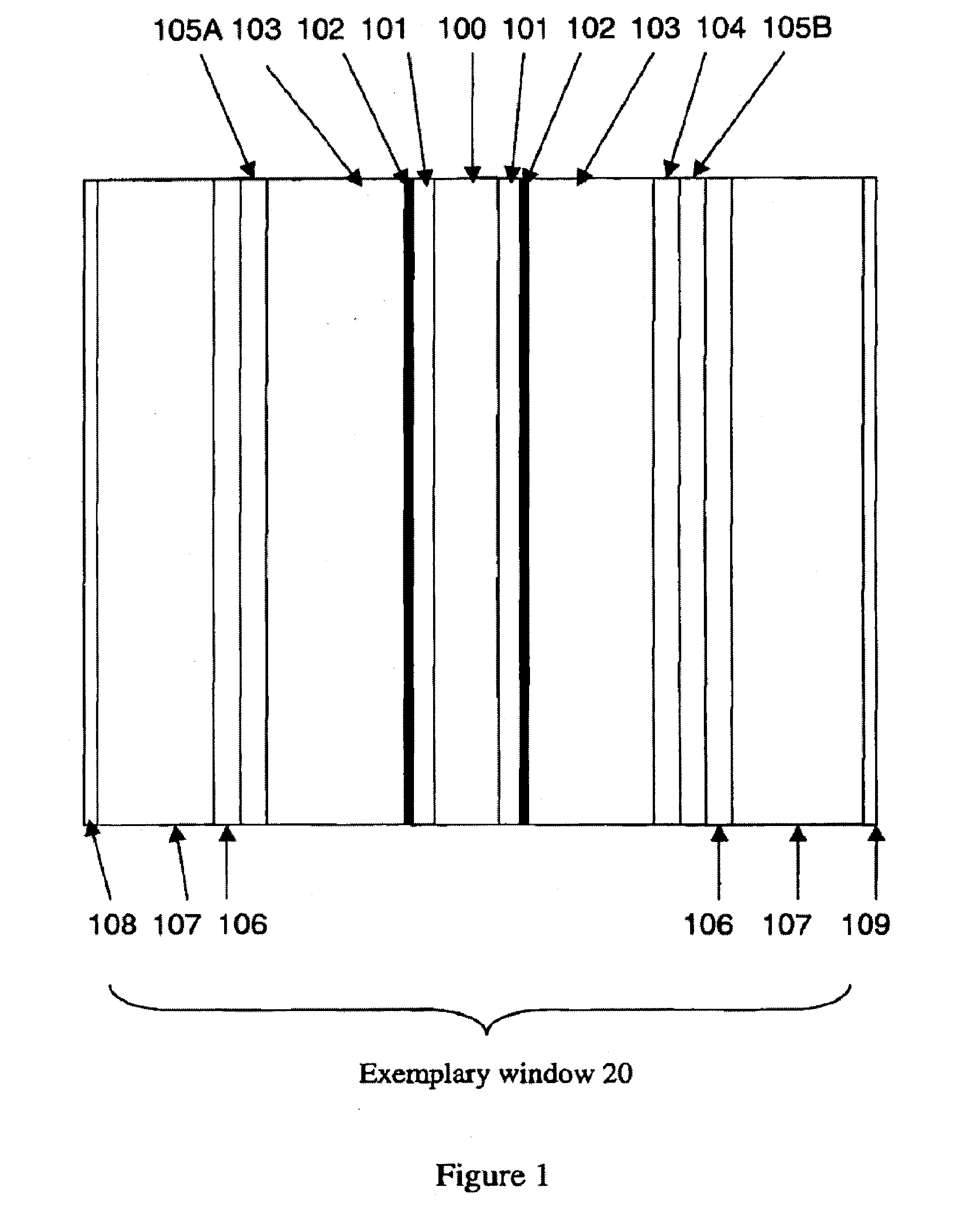
[0052]FIGS. 5A-6B show a controllable tint optical structure, including a sandwich of a first absorptive polarizing film 105A, an active layer 200 that changes the polarization of light in response to an external stimulus, a reflective polarizing film 104, and a second absorptive polarizing film 105B transmitting the same polarization state as the reflective polarizing film 104. The transmission axis of the second absorptive polarizing film 105B is parallel to that of the reflective polarizing film 104 so that the reflective / absorptive polarizing film combination selectively reflects the light exiting the active layer but absorbs the reflection of the light entering from the second absorptive polarizing film. With the polarizer orientations in FIGS. 5A-5B, when the active layer is activated, the polarization of the light is rotated. The light entering from the first absorptive polarizing film side is reflected by the reflective polarizer, which subsequently transmits through the abs...
third embodiment
[0053]FIGS. 7A-8B show a controllable tint optical structure, including a sandwich of a first absorptive polarizing film 105A, a first reflective polarizing film 104A whose transmission state is substantially the same as the transmission state of the first absorptive polarizer 105A, an active layer 200 that changes the polarization of light in response to an external stimulus, and a second reflective polarizing film 104B, and a second absorptive polarizing film 105B whose transmission state is substantially the same as the transmission state of the second reflective polarizer 104B. In this structure, the reflection of the light from the surfaces of absorptive polarizer films of 105A and 105B is minimized regardless of the state of the active layer. With linear polarizers and parallel orientations in FIGS. 7A-7B, when the active layer is activated, the polarization of the light entering to the active layer is rotated, and the light is reflected, making the device opaque in transmissi...
PUM
 Abstract
Description
Claims
Application Information