Array of progressive ophthalmic lens elements

Active Publication Date: 2009-11-26
CARL ZEISS VISION AUSTRALIA HO +1
View PDF3 Cites 14 Cited by
  • Summary
  • Abstract
  • Description
  • Claims
  • Application Information

AI Technical Summary

Benefits of technology

[0073]It will be recognised that the present invention includes a number of advantages in that the invention is able to be used by a dispenser to select, from an array of progressive ophthalmic lens elements, a progressive ophthalmic lens element having lens design parameters that correspond to lifestyle and / or biometric parameters of a wearer. As a result, a dispenser is able to select a lens element from the array that is suited for the lifestyle and / or biometric parameters of the lens wearer.GENERAL DESCRIPTION OF THE INVENTION
[0092]The angular size of the distance zone may be modified by rotating intersecting asymptotes of a hyperbola fitted to the root mean squared (RMS) blur ray traced for the infinite object distance contour equal to the dioptric value of a quarter of the nominal addition power over a range of +20° to −16° to thereby increase or decrease the angular size of distance zone. In an embodiment, modifying the near zone boundary is achieved by rotating asymptotes of a hyperbola fitted to the root mean squared (RMS) blur ray traced for a particular reading distance of the lens wearer of a particular nominal addition power over a range of +20° to −16° to thereby increase or decrease the angular size of the nearzone.
[0105]In one embodiment, within an array the near reference point inset will have a value or characteristic that is attributable to, or associated with, a value or category of a lens wearer's reading distance. In this way, a pair of progressive ophthalmic lens elements may exist in the array that, when combined to form spectacles, provides an acceptable fusion of images from the left and right eyes of a lens wearer at a reading distance in a vertical plane cutting a line connecting the corridor of the left and right eyes at the mid-point.

Problems solved by technology

However, since a single base curve can ensure satisfactory optics only over a range of prescription powers much narrower than is required, lens manufacturers typically create a range of lens element series or base curves to satisfy this requirement.
Unfortunately, progressive ophthalmic lens elements included in a series of semi-finished lens elements are somewhat restricted in that for each “base curve” series, only a single progressive ophthalmic lens element, and thus a single progressive surface design, is available for each addition power.
Therefore, the progressive surface of each progressive ophthalmic lens element in the series may not be optimised for a particular lens wearer.
Unfortunately, given the large number of progressive ophthalmic lens products on the market and the almost infinite combinations and permutations of the design parameters, and the variety of tasks for which a lens may be used, selecting a lens design (from a dispensers perspective) or designing a lens (from a designers perspective) which is suitable for an individual wearer's needs has proven to be somewhat difficult.
Therefore, when selecting a progressive lens for a wearer, many dispensers miss the opportunity to fit a lens which has been selected on the basis of the wearer's needs because they instead fit a favourite, trusted lens design.

Method used


Image

  • Array of progressive ophthalmic lens elements
  • Array of progressive ophthalmic lens elements
  • Array of progressive ophthalmic lens elements

Examples


Embodiment Construction

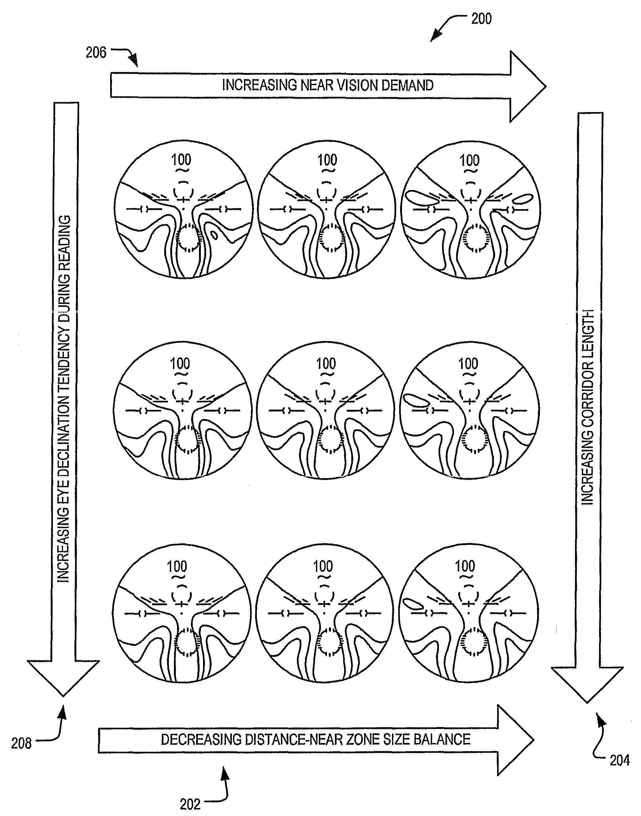
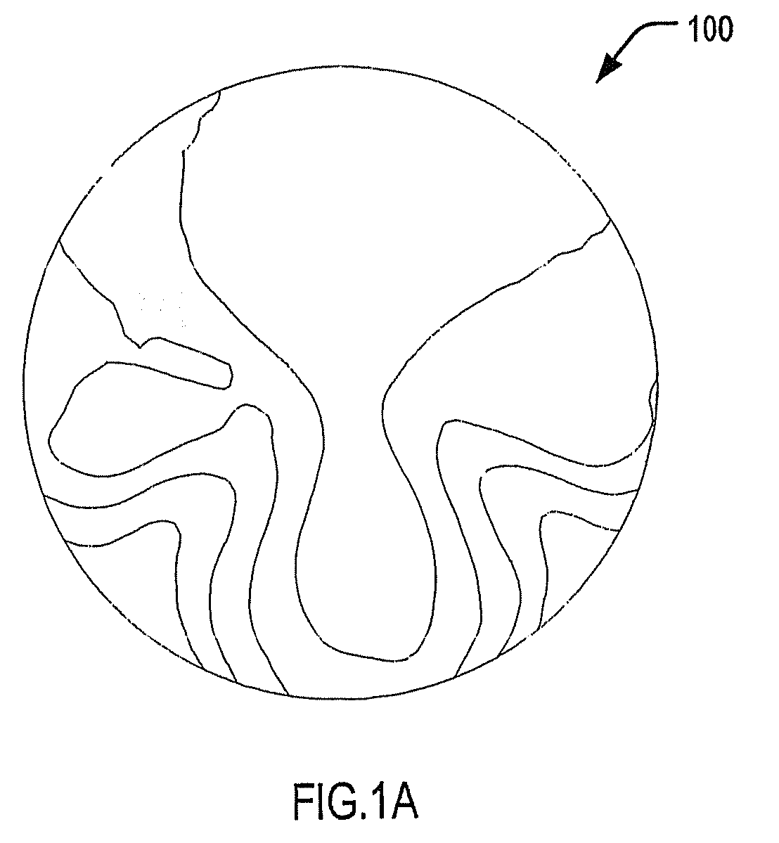
[0128]FIG. 1A shows a contour plot of RMS blur in a conventional progressive ophthalmic lens element 100. The progressive ophthalmic lens element 100 provides an Rx of +2.00 / −1.50×450 and a 2.00 D addition power. Ray tracing has been carried out for the position of wear characterised by a corneal vertex distance of 12 mm and a pantoscopic tilt of 100. An implied object field for ray tracing varies from infinity at the distance reference point (DRP) to 40 cm at the near reference point (NRP). A 0.5 D reserve accommodation has been assumed in estimating the power errors in the near zone. The diameter of the illustrated progressive ophthalmic lens element 100 is 60 mm.

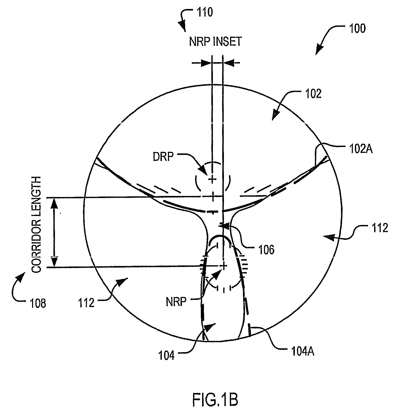
[0129]FIG. 1B depicts a schematic view of a progressive ophthalmic lens element 100 having a different progressive lens design to that shown in FIG. 1A. As shown, the progressive ophthalmic lens element 100 includes an upper viewing zone 102 (“the distance zone”) for providing a refracting power for distance vision, a low...


PUM


Abstract

An array of progressive ophthalmic lens elements is disclosed. The progressive ophthalmic elements contained in the array having substantially the same addition power and substantially the same optical prescription for distance vision. Each of the progressive ophthalmic lens elements has a progressive lens design characterised by a set of parameters defining a distance zone providing a refracting power for distance vision, a near zone providing a refracting power for near vision and a corridor having a refracting power varying from that of the distance zone to that of the near zone. The progressive ophthalmic lens elements provide, for a range of values or categories of at least two lifestyle and / or biometric parameters of lens wearers, different progressive lens designs in which at least two of the lens design parameters each have a respective value or characteristic attributable to, or associated with, a particular value or category of a respective one of the lifestyle and / or biometric parameters.

Description

[0001]This application claims priority from Australian Provisional Patent Application No. 2005902269 filed on 5 May 2005, and the contents of that application are to be taken as incorporated herein by this reference.FIELD OF THE INVENTION[0002]The present invention relates to an array of progressive ophthalmic lens elements and in particular to an array of progressive ophthalmic lens elements having progressive lens designs that are attributable to, or associated with, lifestyle and / or biometric parameters of lens wearers.BACKGROUND OF THE INVENTION[0003]Conventional progressive addition lenses are one-piece lenses having an upper viewing zone (“the distance zone”), a lower viewing zone (“the near zone”), and a progressive corridor (“the intermediate zone”) therebetween which provides a gradual power progression from the distance zone to the near zone without any dividing line or prismatic jump.[0004]Although early progressive ophthalmic lenses were somewhat crude in design, they ha...

Claims


Application Information

Patent Timeline
IPC IPC(8): G02C7/06A61B3/00
CPCG02C7/024G02C7/027G02C2202/08G02C7/063G02C7/066G02C7/061
Inventor VARNAS, SAULIUS RAYMONDSPRATT, RAY STEVEN
Owner CARL ZEISS VISION AUSTRALIA HO
Why Eureka
Try Eureka