Orthopedic clamps

a technology of orthopedic surgery and clamps, applied in the field of orthopedic surgery, can solve the problems of unnecessarily limited movement of the spine, unfavorable patient safety, and increased risk of surgery, and achieve the effects of less surgical cuts, less exposed bone tissue, and less invasive surgery

Inactive Publication Date: 2010-11-16
FACET MED
View PDF11 Cites 3 Cited by
  • Summary
  • Abstract
  • Description
  • Claims
  • Application Information

AI Technical Summary

Benefits of technology

[0032]In accordance with the present invention, there is provided a new kind of clamp—“saddle” clamp for mounting on bones with curved surface in a bone fixing or spinal fusion operation, for carrying a bone-fixing member, i.e. plate. The saddle clamp has a rigid body with at least two holes for passing fixing elements to be tightened to the bone and at least one assembly element integral with the body for attaching the bone-fixing member. The rigid body has a contact surface configured to have at least three points of contact with the curved surface of the bone when the saddle clamp is mounted thereon, at least two of the holes passing through the contact surface via or adjacent two of the three points of contact. This allows to provide, upon tightening of the fixing elements, at least three spaced apart, non-collinear areas of contact, and firm attachment of the clamp to the bone.
[0035]One embodiment of the present invention is a saddle clamp for use in vertebral fusion operation allowing to perform it in a simple, safe and speedy manner, avoiding many of the above-mentioned disadvantages of the prior art methods. The application method of the new saddle clamp provides less likelihood of complications and damage to the patient; especially to the spinal cord or nerves emanating therefrom, or to adjacent blood vessels; it is simple to perform without requiring a high level of surgeon skill, and will not cause catastrophic damage in the event of a poorly executed procedure, it is short and requires minimal X-radiation exposure, and utilizes simple instruments and therefore, does not require a highly skilled operation room team.
[0056]The saddle clamps of the present invention needs less invasive surgery (less surgical cuts, less exposed bone tissue, less hemorrhages, etc.). In tubular bone surgery, the clamps are applicable for fixation of long bones with multiple fractures.
[0057]In spinal fusion surgery, the method of the present invention allows usage of short and thin screws which penetrate only into the top ends of their respective bone bases. Since the bone structure of the top end of the pedicle is dense (cortical bone), two inclined screws may hold the element firmly and snuggly in its position, despite their short length.
[0058]Use of the clamp of the present invention has a number of significant advantages over the prior art methods of performing spinal fusion. Firstly, the short drilling length of the screw holes reduces the likelihood of damage to the spinal cord, or any other adjacent feature, such as nerve ends or blood vessels. Furthermore, the short drilling length, the thinner screw and the drilling into dense cortical bone regions of the pedicle, means that there is little danger of breakage of the pedicle. Additionally, the use of two inclined screws inserted into cortical bone, despite their short length and smaller diameter, provides attachment strength which is as adequate for the required task as that of the prior art use of single pedicle screws on each side. Because of the reduced danger of complications, and the simple physical procedure, the operation can even be performed by less experienced surgeons. Furthermore, the greater simplicity and safety of the use of the clamp of the present invention may make its use more acceptable for application to spinal fusion in the upper parts of the back, which has been hitherto more rarely performed, if at all allowable by the regulatory authorities. Finally, the reduced duration of the operation, typically down to half of that for a similar operation performed using prior art methods, and the reduced radiation exposure, make the use of the clamp of the present invention significantly safer to the patient.

Problems solved by technology

(a) Hook fixation—because of the comparative weakness of the holding power of the hooks, a larger number of vertebrae need to be fused to achieve acceptable results, than when using the other methods.
This may lead to unnecessarily limited movement of the spine in the operated region, with consequent problems of mobility.
Furthermore, what should be a comparatively simple operation and localized operation becomes much more extensive, with concomitant increase in blood loss, time under anesthesia, and the need for an external brace for some time after the operation.
Failure of the hooks to hold well may cause them to move during the healing period.
b) Pedicle screwing—the insertion of the pedicle screw is generally a difficult, error prone and time consuming procedure.
Furthermore, the method results in a high level of X-ray exposure to the surgeon and staff.
(i) Breakage of the pedicle due to a misdirected drill, or poor drilling technique.
(ii) Penetration of the spinal cord, with resultant nerve damage.
(iii) Damage to neighboring nerve roots, causing pain and nerve damage.
(iv) Penetration of the abdominal cavity, with the resultant danger of damage to major blood vessels and hemorrhaging.
It has been reported by R. W. Gaines in the article “The Use of Pedicle Screw Internal Fixation for Spinal Disorders”, Journal of Joint and Bone Surgery, Vol. 82-A, No. 10, 2000, that about 3% of misplaced screws are more than 5 mm away from their planned position, almost inevitably causing nerve damage.
Insertion of pedicle screws in the thoracic and cervical vertebrae is even riskier because of the compact and delicate structure of the spine in these regions.
For this reason, few experienced surgeons perform spinal fusion by this means at these levels, and in the USA, the procedure is not even FDA authorized for these regions.
Either access is needed to the front of the spine through the abdomen or thoracic cavity, with its concomitant possibilities of complications, or access to the vertebrae from the rear, in which case a wide laminectomy procedure must be performed, and displacement of the entire dura matter in the region of the cage insertion
Furthermore, in all of the methods, there are the general difficulties relating to surgery on the vertebral column, include micro-movement of the vertebral column during the operation, the inherently small target objects of the procedure such as the pedicles, and delicate nerve tissue close to the operation region.
Such screws are likely to cause secondary infections of the operated limb.

Method used


Image

  • Orthopedic clamps
  • Orthopedic clamps
  • Orthopedic clamps

Examples


Embodiment Construction

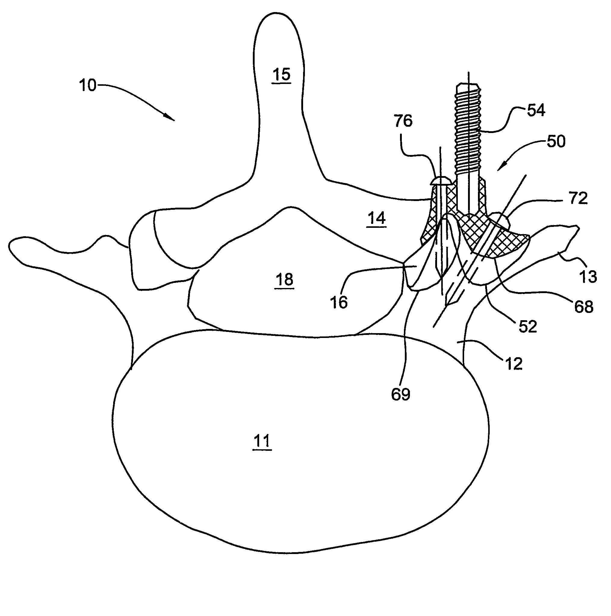
[0070]FIGS. 6A to 6E are schematic views of a vertebral fusion clamp 50 according to an embodiment of the present invention, the views being taken from different directions to illustrate the structure of the element. The views are taken respectively from the right side (FIG. 6A), from the rear side (FIG. 6B), from the front side (FIG. 6C), from above (FIG. 6D) and from beneath (FIG. 6E). The vertebral fusion clamp 50 comprises a body 52 and an integral threaded rod 54 for attachment of a fusion plate or rods.

[0071]The body 52 has unique shape including a saddle surface 56 and an arcuate surface 58. The saddle surface 56 is defined generally between a down-turned arch 60 and an upturned arch 62 lying in transverse planes and having a common point 64 (saddle point). The arcuate surface 58 is defined generally by a down-turned arch 66 (as seen best in FIG. 6A) and merges smoothly with the saddle surface 56. The top-most points of the arcuate surface 58 are higher than the arch 60.

[0072...


PUM


Abstract

A saddle clamp for mounting on a bone with curved surface in a bone-fixing or spinal fusion operation, for carrying a bone-fixing member. The saddle clamp has a rigid body with at least two holes for passing fixing elements to be tightened to the bone and at least one assembly element integral with the body for attaching the bone-fixing member. The rigid body has a contact surface configured to allow at least three points of contact with the curved surface of the bone when the saddle clamp is mounted thereon, at least two of the holes passing through the contact surface at least adjacent to two of the points of contact so as to provide, upon tightening of the fixing elements, at least three spaced apart, non-collinear areas of contact and thereby firm attachment of the saddle clamp to the bone.

Description

CROSS-REFERENCE[0001]This is a National Phase Application filed under 35 U.S.C. §371 as a national stage of PCT / IL2004 / 000524, filed on Jun. 17, 2004, claiming the benefit under 35 U.S.C. §119(e) of U.S. Provisional Application No. 60 / 478,855, filed on Jun. 17, 2003, the content of each of which is hereby incorporated by reference in its entirety.FIELD OF THE INVENTION[0002]The present invention relates to the field of the orthopedic surgery, in particular as performed by use of mechanical clamps for fixation of neighboring vertebrae or fractured tubular bones.BACKGROUND OF THE INVENTION[0003]Vertebral fusion is a common spinal surgical procedure, performed in order to overcome problems related to impaired mutual interaction between neighboring vertebrae. A pair of adjacent human vertebrae is shown in FIG. 1. Each of the vertebrae 10 and 20 has, respectively, a vertebra body 11 (21), two pedicles 12 (22), two transverse processes 13 (23), two laminae 14 (24), a spinal process 15 (25...

Claims


Application Information

Patent Timeline
Patent Type & Authority Patents(United States)
IPC IPC(8): A61B17/80A61B17/68A61B17/70
CPCA61B17/68A61B17/7044A61B17/7064A61B17/7007A61B17/80
Inventor SHARIM, HAMID
Owner FACET MED
Why Eureka
Try Eureka