Plate system for securing bone or bone fragments

a plate system and bone technology, applied in the field of plates, can solve the problems of affecting the correct position of the plate, the fracturing of the wrist and the bones meeting therein, and the difficulty of attaching the pla

Inactive Publication Date: 2006-11-16
INION
View PDF13 Cites 62 Cited by
  • Summary
  • Abstract
  • Description
  • Claims
  • Application Information

AI Technical Summary

Benefits of technology

[0020] The basic idea of an embodiment of the system in accordance with the invention is that the thread in the threaded portion of an attachment screw is arranged to vary such that the thread crest is higher in the portion closer to the screw tip than in the portion further away from the tip. There is an advantage that a high crest attaches optimally to the spongy bone whereas a lower crest attaches optimally to the cortical bone.
[0021] The basic idea of an embodiment of the method in accordance with the invention is that an actual attachment hole of the plate is prepared at an angle to the plate, which angle differs from that of the prehole of the attachment hole to the plate. There is an advantage that the attachment screw can be arranged in such a position with respect to the plate that the prehole does not definitely determine the direction of the attachment screw, but the screw and consequently the plate can be attached to the bone tissue in the best possible manner in view of the medical and operational criteria associated with the procedure.

Problems solved by technology

The wrist and the bones meeting therein may fracture, for instance, as a result of falling or stumbling.
The known plates involve some problems.
First, it is difficult to attach the plate in correct position to bone fragments to be fixed to one another, because it is difficult to hold the plate steady on the bone while the attachment holes are being drilled.
Another problem relates to the attachment of the plate to the bone.
This delays healing of the fracture.

Method used


Image

  • Plate system for securing bone or bone fragments
  • Plate system for securing bone or bone fragments
  • Plate system for securing bone or bone fragments

Examples


Embodiment Construction

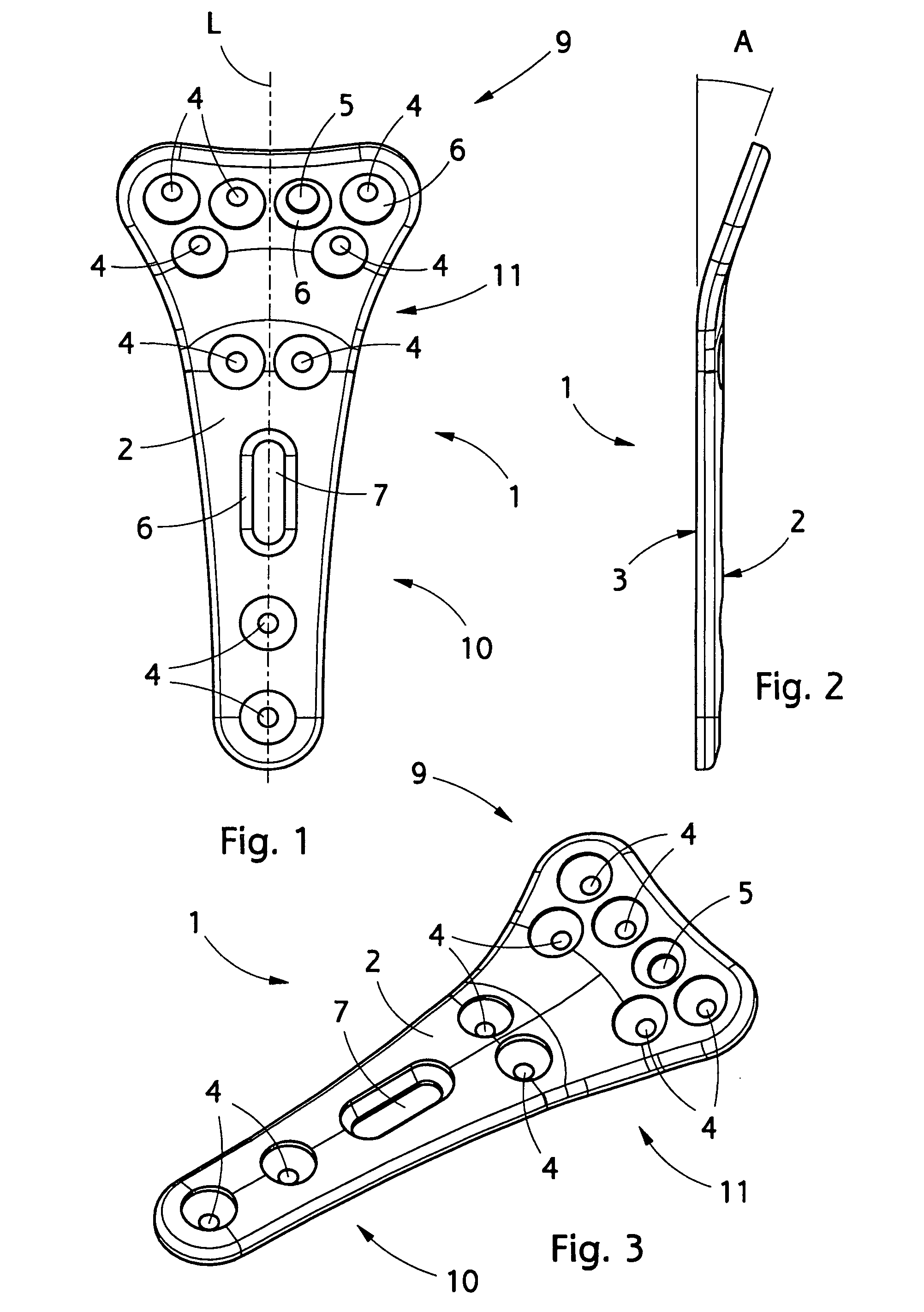
[0031]FIG. 1 shows schematically a plate in accordance with the invention seen in the direction of the upper surface, FIG. 2 is a schematic side view of the same plate and FIG. 3 is a perspective view in the direction of the upper surface.

[0032] The plate 1 is intended for fixing a distal part loose from the shaft of the radius bone to the shaft of the radius bone such that the plate 1 is attached to the palm side of the radius bone. Depending on the type of the fracture there may be one or more distal bone fragments to be attached to the shaft of the radius bone. In connection with the following figures an operation like this will be described, but it is obvious that the plate, the arrangement and the method in accordance with the invention may also be used in treating other bone fractures, osteotomies and fusions.

[0033] The plate 1 is most preferably manufactured of biodegradable polymer material absorbable in the body that is made by polymerizing or copolymerizing, for instance...


PUM


Abstract

A plate for securing bone or bone fragments, its use, a system and an attachment method of the plate. The plate comprises a first part intended for attaching to at least one first bone fragment, and a second part intended for attaching to at least one second bone fragment, and an upper surface and a lower surface. The upper surface comprises a plurality of holes, of which holes some are preholes, in at least one of which preholes an actual, threaded attachment hole is arranged to be prepared in situ, and at least one free hole, which is a through hole extending from the upper surface to the lower surface, the smallest diameter of the free hole being larger than the diameter of the preholes.

Description

RELATED APPLICATION(S) [0001] This application claims priority from Finnish patent application number FI 20055214, filed May 6, 2005, which is hereby incorporated herein by reference in its entirety. BACKGROUND OF THE INVENTION [0002] The invention relates to a plate for fixing bone fragments to one another, the plate comprising a first part intended for attaching to at least one or more first bone fragments and a second part intended for attaching to one or more second bone fragments, an upper surface and a lower surface. [0003] The invention also relates to the use of the plate. [0004] The invention further relates to a system for fixing bone fragments to one another. [0005] The invention still further relates to a method for fixing bone fragments to one another. [0006] The wrist and the bones meeting therein may fracture, for instance, as a result of falling or stumbling. Very often it is the radius bone meeting the wrist joint that fractures such that its distal part breaks in o...

Claims


Application Information

Patent Timeline
Patent Type & Authority Applications(United States)
IPC IPC(8): A61B17/80A61B17/00A61B17/16A61B17/86A61C
CPCA61B17/1655A61B17/1686A61B2017/00004A61B17/863A61B17/8085A61F2/28
Inventor PITKANEN, HEIKKIHAPPONEN, HARRIVUORISALO, VESA
Owner INION
Why Eureka
Try Eureka