Endoscope device
a technology of endoscope and endoscope, which is applied in the field of endoscope devices, can solve the problems of reducing insertion ability and difficulty in observing the state of treatment performed by the treatment tools by using the observation main body, and achieve the effects of preventing the insertion ability of the insertion part, enhancing the effect of treatment, and enhancing the visibility of the distal portion of the arm member
- Summary
- Abstract
- Description
- Claims
- Application Information
AI Technical Summary
Benefits of technology
Problems solved by technology
Method used
Image
Examples
first embodiment
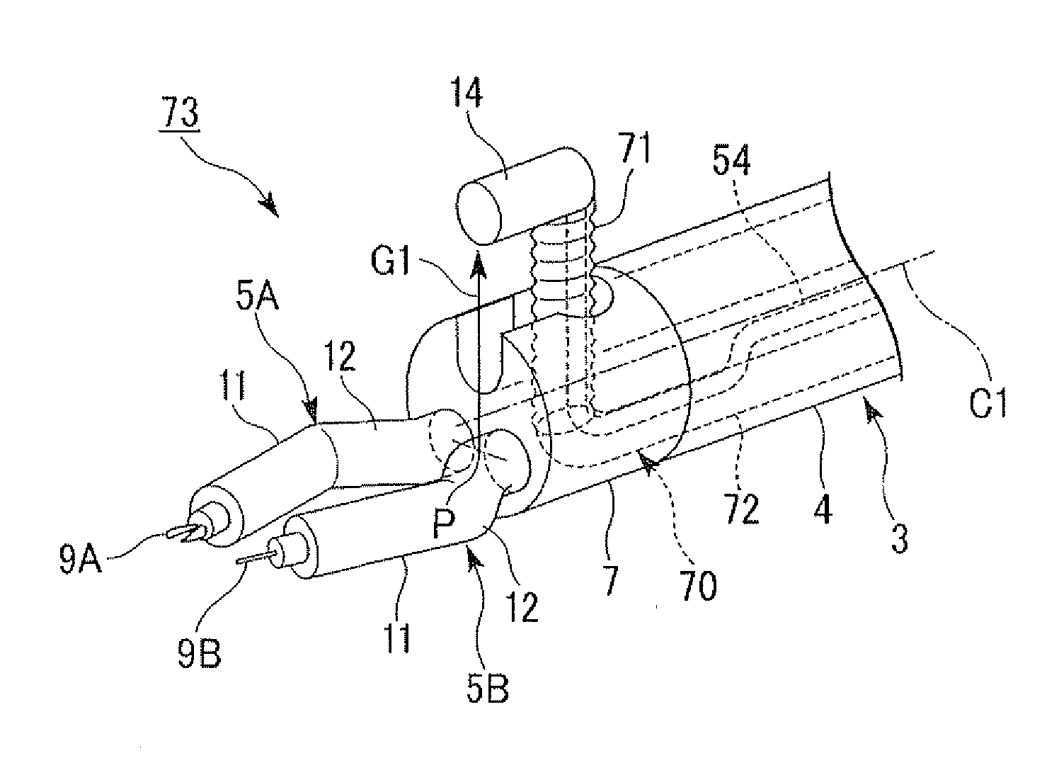
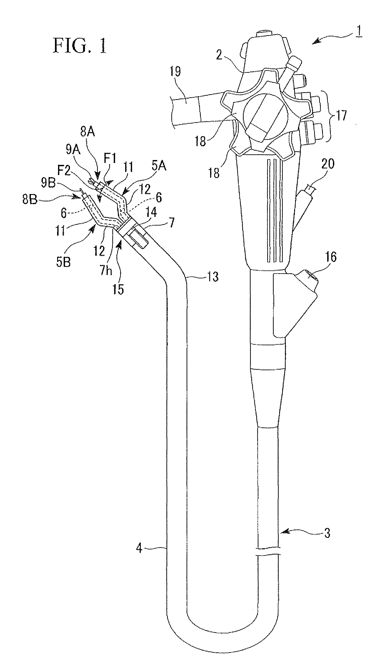
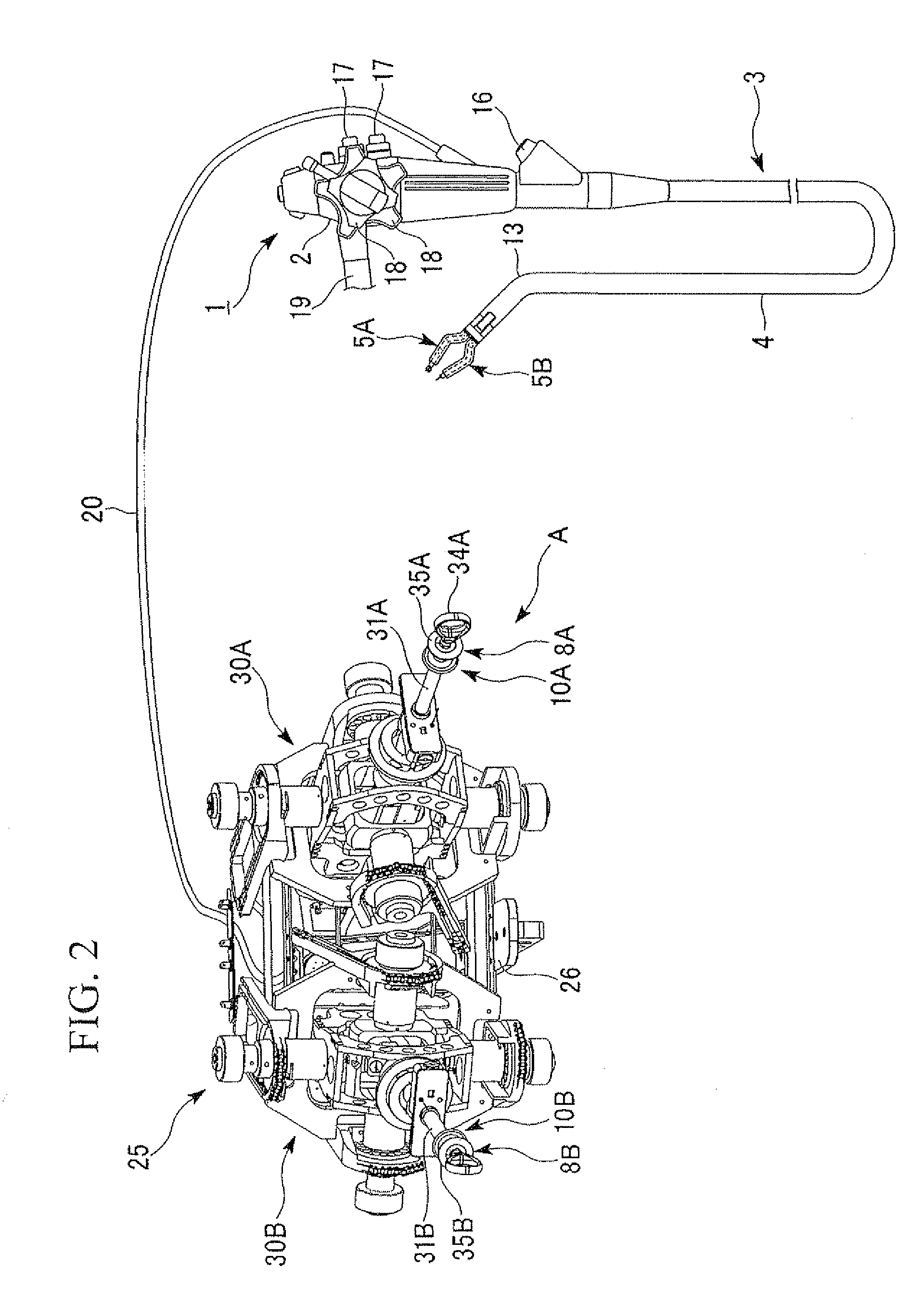
[0044]As shown in FIG. 1, an endoscope device 1 has an operating part 2 and a tubular insertion part 3 which extends from one end of the operating part 2 in a unitary manner. The insertion part 3 is elongated and has flexibility. The insertion part 3 has the same construction as an insertion part described in U.S. patent application Ser. No. 11 / 435,183 or U.S. patent application Ser. No. 11 / 652,880. That is, the insertion part 3 has a sheath 4, a distal end construction part 7 which is disposed in the distal portion of the sheath 4, and bendable first and second arm members 5A and 5B which are provided on a distal end surface 7h of the distal end construction part 7 so as to protrude forward. Instrument channels 6 are formed inside the arm members 5A and 5B respectively, and extend to connect with a later-described connection sheath 20 via the insertion part 3 and operating part 2. Treatment tools 8A and 8B are inserted into the instrument channels 6 respectively, and treatment part...
second embodiment
[0075]Next, a second embodiment of the present invention will be described. Elements the same as those of the first embodiment and the modification example thereof are denoted by the same reference numerals and the descriptions thereof are omitted, and only different points are described.
[0076]As shown in FIG. 8, an endoscope device 64 of the present embodiment is provided with an extension / contraction mechanism 60 which moves the observation main body 14 toward the moving direction G1 opposite to the first and second arm members 5A and 5B in the radial direction. The extension / contraction mechanism 60 has a telescopic portion 62 formed by nesting a plurality of cylindrical members 61 having diameters different from each other such that the entirety of the telescopic portion 62 freely extends and contracts in the moving direction G1, and an operating wire 63 which protrudes and retracts the telescopic portion 62 in the moving direction G1 by pushing and pulling the proximal portion ...
third embodiment
[0085]Next, a third embodiment of the present invention will be described. Elements the same as those of the first and second embodiments and the modification examples thereof are denoted by the same reference numerals and the descriptions thereof are omitted, and only different points are described.
[0086]As shown in FIG. 12, an endoscope device 86 of the present embodiment is provided with an observation main body 14 which observes the direction to which the observation main body faces, an observation main body rotation mechanism 80 which rotatively supports the observation main body 14 such that the observation main body 14 faces the moving direction G1 opposite to the first and second arm members 5A and 5B in the radial direction and faces the front of the insertion part 3, and a reflection member 81 disposed in the distal portion of the insertion part 3 so as to freely protrude and retract.
[0087]The observation main body 14 is supported in the distal end construction part 7 by a...
PUM
 Abstract
Description
Claims
Application Information
 - R&D
- Intellectual Property
- Life Sciences
- Materials
- Tech Scout
- Unparalleled Data Quality
- Higher Quality Content
- 60% Fewer Hallucinations
Browse by: Latest US Patents, China's latest patents, Technical Efficacy Thesaurus, Application Domain, Technology Topic, Popular Technical Reports.
© 2025 PatSnap. All rights reserved.Legal|Privacy policy|Modern Slavery Act Transparency Statement|Sitemap|About US| Contact US: help@patsnap.com


