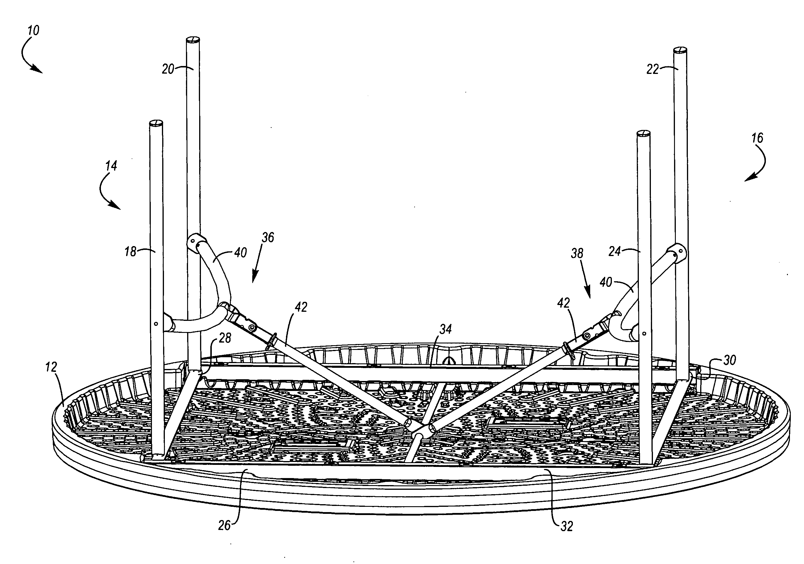
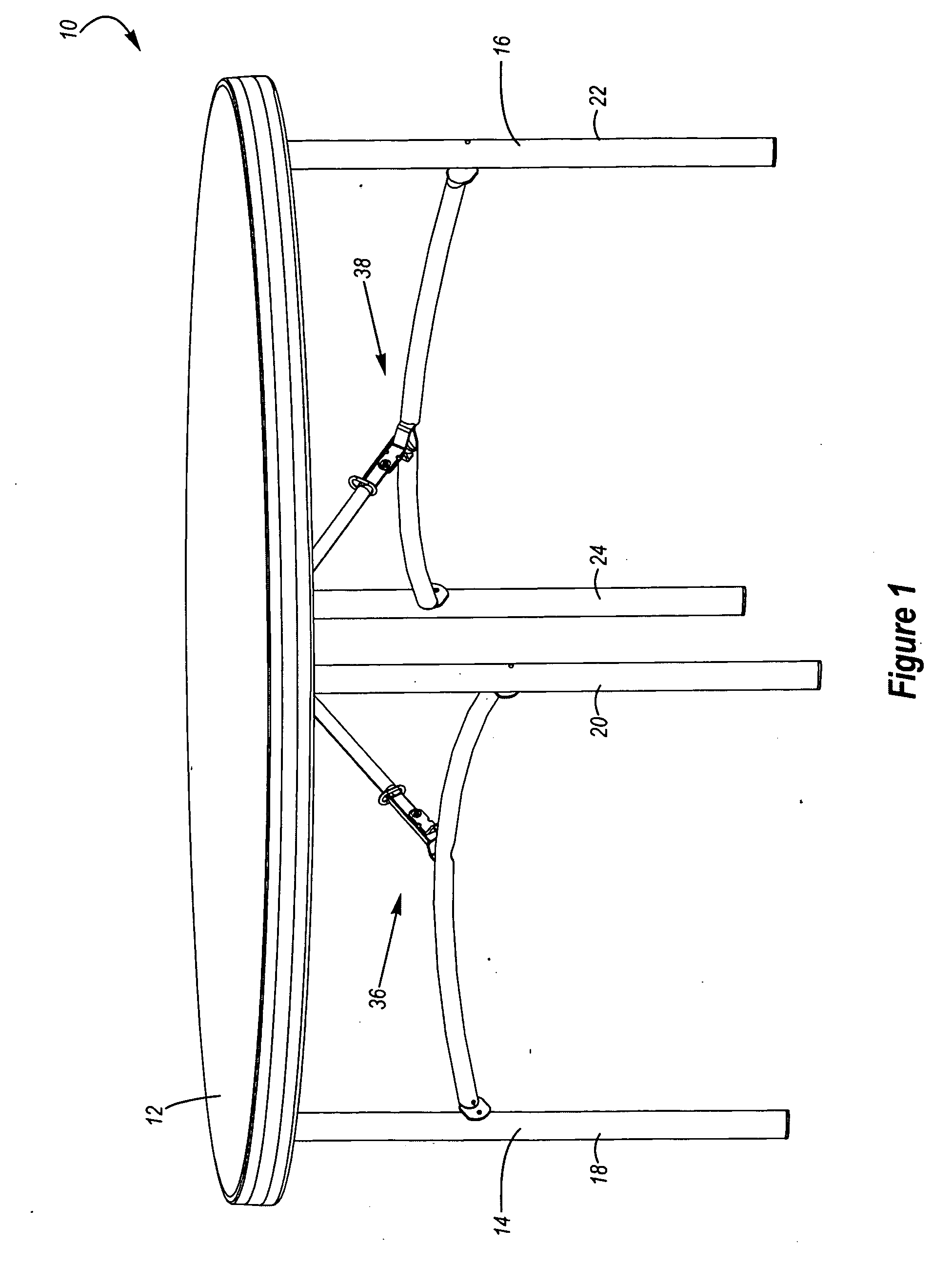
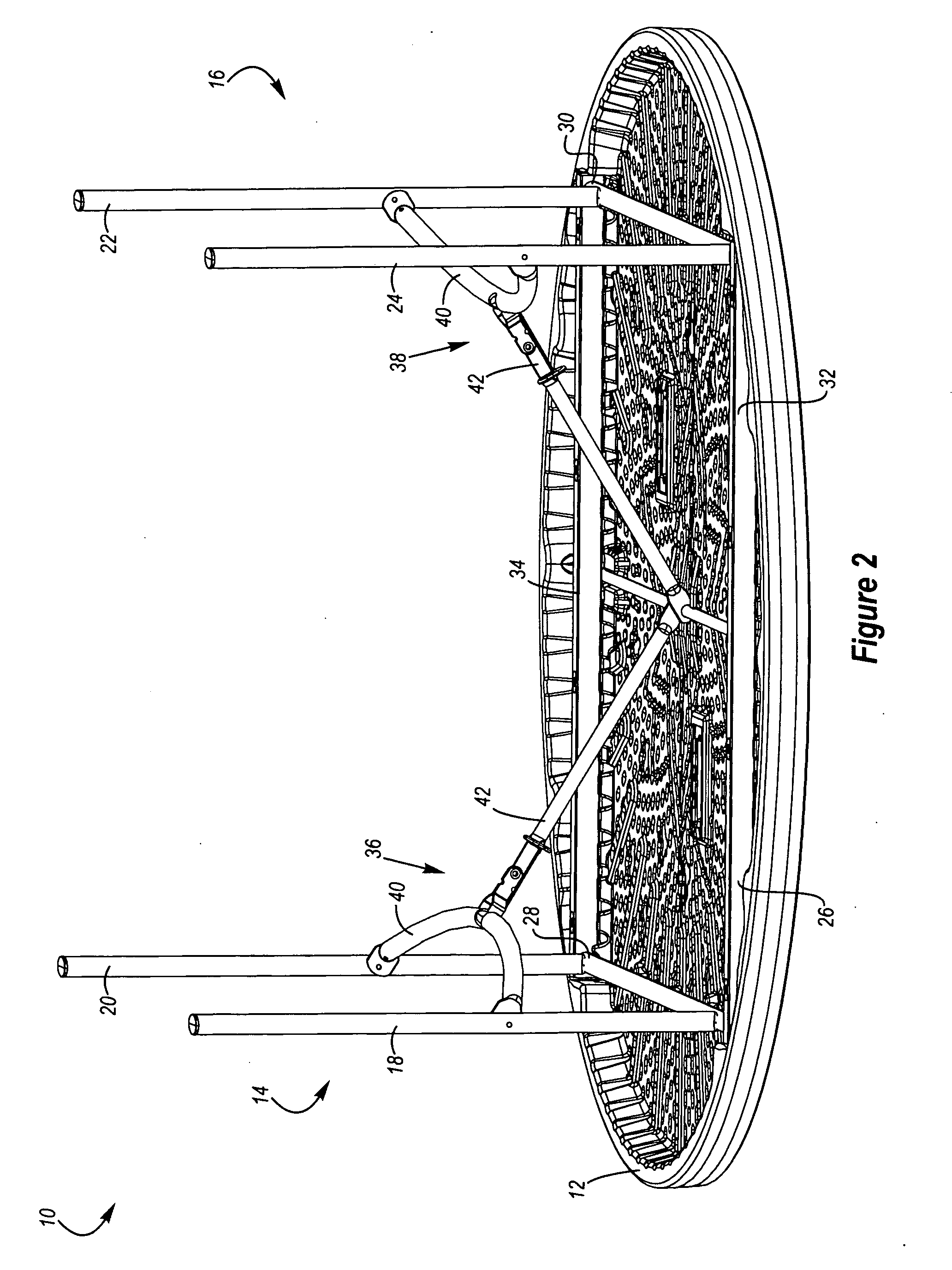
[0009]Another aspect is table that may include a table top and a support structure with a pair of legs and a brace assembly. The brace assembly may include a first portion connected to the legs and a second portion connected to the table top. The first and second portions of the brace assembly may be movably interconnected, which may allow the brace assembly and / or the legs to move between the extended and collapsed positions relative to the table top. In particular, as the legs are moved between the extended and collapsed positions, the first and second portions of the brace assembly may pivot, rotate, slide and / or otherwise move relative to each other to allow the brace assembly and / or the legs to move between the extended and collapsed positions. Additionally, if the first and second portions of the brace assembly are movably interconnected, then the legs and the brace assembly may be more easily positioned
proximate or against a lower portion of the table top when the legs and brace assembly are in the storage position. Advantageously, when the legs and brace assembly are in the storage position, the legs and brace assembly may be generally aligned in the same plane and may be positioned adjacent to and / or contacting the lower portion of the table top, which may permit the table to be more efficiently stored and / or shipped. That is, because the legs and brace assembly may be disposed adjacent and / or contacting a lower portion of the table top when the legs and brace assembly are in the collapsed position, that may minimize the thickness of the table and allow the table to be more easily shipped or stored because less space may be required.
[0010]Yet another aspect is a table that may provide increased leg room. For example, the table may include a brace assembly and a portion of the brace assembly may be curved or arched away from the outer edges of the table top, which may increase the leg room available under the table top. In addition, the table may include a brace assembly that is curved or arched upwardly, which may also increase the amount of leg room. Significantly, the brace assembly may be curved or arched both upwardly and away from the outer edges of the table top to increase leg room. Desirably, the brace assembly may be curved upwardly and inwardly towards a center portion of the table top. Advantageously, the curved or arched brace assembly may allow a shorter connecting member to be used to connect the curved portion of the brace assembly to the table top.
[0011]Still another aspect is a table that may allow users to sit in multiple different locations relative to the table top and still provide ample leg room to such users. For instance, the table may include legs and a brace assembly may help connect the legs to the table top. The brace assembly preferably increases the versatility of the table by allowing persons to sit in various positions relative to the table top without limiting the leg room of the persons sitting at the table. That is, the brace assembly may be sized and configured to allow persons to sit at any locations relative to the table top without limiting the leg room of such persons.
[0012]Still yet another aspect is a table that may include a support structure with a first leg, a second leg and a brace assembly. The brace assembly may include a first portion that is connected to the first and second legs and a second portion that is connected to the table top. In greater detail, the first portion is preferably movably connected to the legs and the second portion is preferably movably connected to the table top. The first portion of the brace assembly preferably has a rigid, inflexible configuration and securely connects the first and second legs, which may help strengthen and / or reinforce the support structure. The secure connection of the legs by the first portion of the brace assembly may also help create a table that is sturdy and stable. Advantageously, the secure connection of the legs by the first portion of the brace may help eliminate the need for additional structure or supports interconnecting the first and second legs. That is, no additional supports or structures may be required to connect the legs. Because additional structure or supports may not be needed, the table may have more leg room. The additional legroom may also help provide more versatile seating at the table. For example, because the additional structure or supports may be eliminated, this may allow persons to sit in additional locations relative to the table top without the additional structure or supports limiting leg room or preventing persons from sitting in certain locations.
[0014]Another further aspect is a table that may include a brace assembly with a first portion and a second portion that are connected by a bracket. For example, the first portion of the brace assembly may include a first section and a second section that are connected by the bracket. The second portion of the brace assembly may also be connected to the bracket. The bracket may include flanges to facilitate connection of the bracket to the first and second sections of the brace assembly. The bracket may also include a
flange that straddles and / or engages the second portion of the brace assembly when the brace assembly is in the storage position, which may help position the legs and / or the brace assembly
proximate or against a lower portion of the table top when the legs and brace assembly as in the storage position.
[0015]Yet another further aspect is a table that may include legs which are pivotally connected to a table top and a brace assembly that is pivotally connected to the legs. For example, the brace assembly may include a first portion that is pivotally connected
proximate a midpoint of a first leg and a second leg. The first portion of the brace assembly may be curved or arched upwardly and towards a center portion of the table top. A second portion of the brace assembly is preferably pivotally connected to the first portion of the brace assembly by a bracket. The pivotal connection of the first and second portions of the brace assembly is preferably disposed proximate the first portion of the brace assembly but spaced apart from the first portion of the brace assembly by a distance. This may allow, for instance, the pivotal connection of the first portion of the brace assembly to the legs to be aligned along an axis and the pivotal connection of the first and second portions of the brace assembly to be space apart from the axis and disposed towards the center portion of the table top. This may also allow the first portion and the second portion of the brace to have approximately the same length, which may facilitate shipping and / or manufacturing of the table.


