
Combination bench and table

a bench and table technology, applied in the field of furniture, can solve the problems of deck furniture, conventional picnic tables may not provide the comfort and relaxation provided, and the picnic table is difficult and awkward to use, and achieve the effect of reducing disadvantages and problems

Active Publication Date: 2011-12-29
LIFETIME PRODUCTS
View PDF6 Cites 5 Cited by
  • Summary
  • Abstract
  • Description
  • Claims
  • Application Information

AI Technical Summary

Benefits of technology

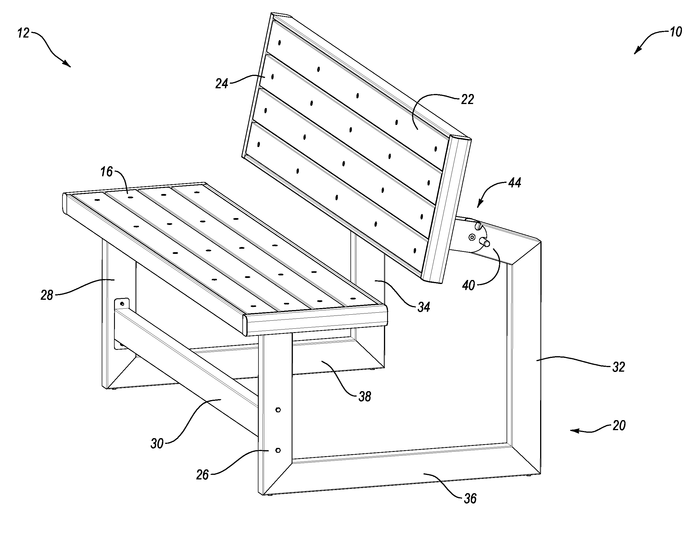
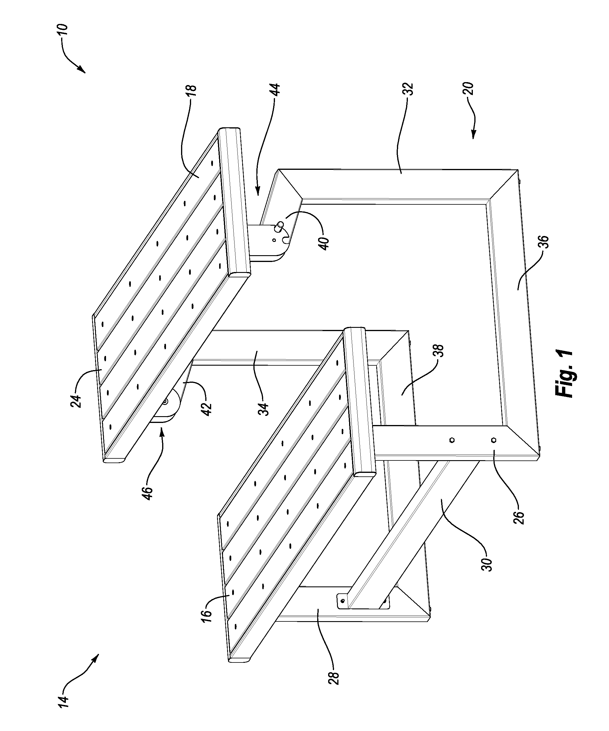
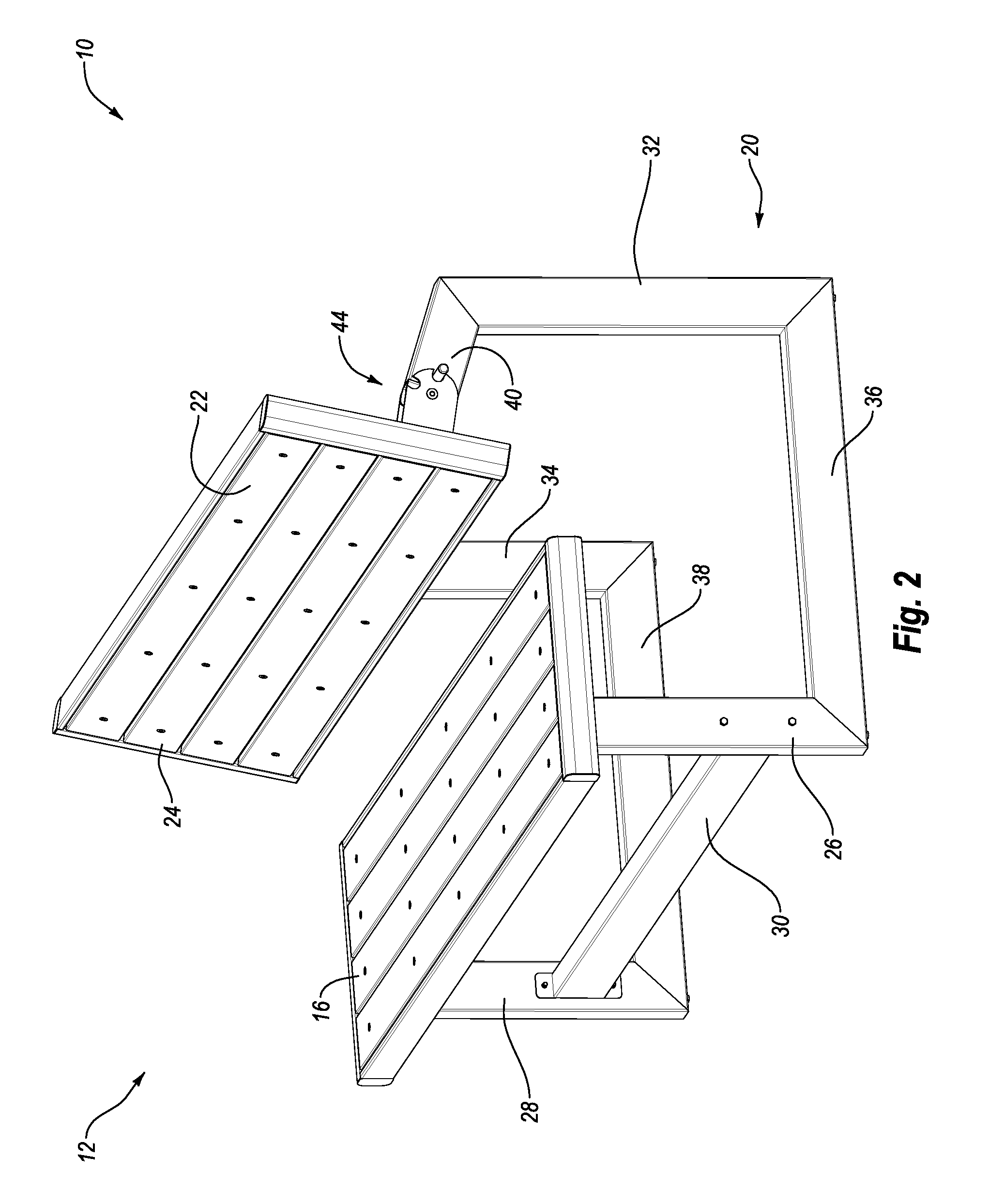
[0012]Another aspect is combination bench and table that may be quickly and easily moved between the bench configuration and the table configuration. For example, a person may simply move a handle to allow the structure to be moved between the different configurations. Advantageously, moving the structure between the bench and table configurations may be accomplished by a single person.
[0013]Still another aspect is a combination bench and table that may include a structure that forms the backrest in the bench configuration and the table in the table configuration. The structure may be pivotally disposed in a unique position about a single pivot point or axis to create the backrest and table. For example, the pivot point or axis may be disposed proximate the lower portion of the backrest and front edge of the table. Significantly, this location may allow rapid and convenient movement between the bench and table configurations.
[0014]Yet another aspect is combination bench and table that may include a frame that connects the seat and the structure that forms the backrest and table. The frame preferably includes a distinctive cantilever design, which may allow the combination bench and table structure to be conveniently used. For instance, the cantilevered portion of the frame may be angled upwardly and that may allow for ease of use when the structure is in the table configuration. The unique cantilever design may also allow the pivot point or axis of the movable backrest and table to be correctly positioned. In addition, the frame may provide a sturdy and stable base for the bench and table structure. Further, the frame may provide unobstructed leg room for persons sitting on the seat in the table configuration and it may allow the structure to be quickly and easily moved between the bench and table configurations.
[0016]A still further aspect is a combination bench and table that may include a support structure which connects the seat and the movable structure which forms the table and backrest. This movable structure that forms the table and backrest may be referred to as a platform. The support structure may include a first set of one or more legs that support the seat and a second set of one or more legs that support the platform. The support structure may include one or more cantilevered supports, which may advantageously provide additional legroom and / or easier entry in the table configuration. The cantilevered supports may be disposed at an upwardly extending angle and may facilitate connection of the platform and the support structure. One of ordinary skill in the art will appreciate, after reading this disclosure, that the cantilevered supports are not required and the support structure may be connected to other suitable portions of the platform.
[0018]Yet another further aspect is a combination bench and table that may include a connecting assembly with one or more brackets. For example, the connecting assembly may include a first set of one or more brackets connected to the platform and a second set of one or more brackets connected to the support structure. The first and second sets of brackets may be connected. For example, the first and second sets of brackets may be rotatably or pivotally connected using one or more fasteners, pins and / or the like. Advantageously, the brackets may allow the platform to rotate relative to the support structure. In particular, the brackets may allow the platform to rotate relative to the cantilevered portion of the support structure.

Problems solved by technology

The support structure of many conventional picnic tables is rather large and obstructive, which can make the picnic table difficult and awkward to use.
Once the meal is finished, however, conventional picnic tables may not provide the comfort and relaxation provided by other patio or deck furniture.
Further, because of the relatively large size of conventional picnic tables, the picnic table may limit the amount of available space on a patio or deck, in a backyard.
Conventional picnic tables are often difficult to move because of their large size and heavy weight.
Picnic tables may also have a limited number of uses because of their large size, shape and configuration.
That is, because most picnic tables may only be disposed in a single configuration, the potential uses of the picnic table may be quite narrow or restricted.
Unfortunately, such benches have a limited number of uses.
For example, benches may not provide a comfortable area to enjoy a meal.
For example, previous furniture that is convertible between a bench structure and a table structure may not provide a quick and easy means for converting the furniture between the different configurations.
Disadvantageously, these complicated structures, which may include a number of small parts, are frequently difficult, time-consuming and expensive to manufacture.
In addition, known convertible furniture is often awkward and cumbersome to use and operate.
Further, known convertible furniture may require a significant amount of space and may require two or more people to move the furniture between the different configurations.
Finally, known convertible furniture may be uncomfortable to use.
For example, the bench may provide a seat that is painful to sit on, especially for extended periods of time, and the table may be difficult to use because of the spacing and distance between the seat and table.

Method used


Image

  • Combination bench and table
  • Combination bench and table
  • Combination bench and table

Examples


Embodiment Construction

[0010]A need therefore exists for an apparatus that eliminates or diminishes the disadvantages and problems described above.

[0011]One aspect is a combination bench and table that may include a bench configuration and a table configuration. Preferably, the combination bench and table is readily movable between the bench and table configurations. In the bench configuration, the bench may include a seat for one, two or more persons. The bench may also include a backrest. The backrest may be spaced apart from the seat by a distance and the backrest may be disposed at an angle relative to the seat. The table configuration may include seat for one, two or more persons and a table disposed in a generally horizontal position.

[0012]Another aspect is combination bench and table that may be quickly and easily moved between the bench configuration and the table configuration. For example, a person may simply move a handle to allow the structure to be moved between the different configurations. ...


PUM


Abstract

A combination bench and table may include a platform that is movable between a bench configuration and a table configuration. The platform may form a backrest in the bench configuration and a table in the table configuration. The platform may be supported by a cantilever support member that extends upwardly at an angle and a connecting assembly preferably connects the platform and the cantilever support member. The connecting assembly may allow the platform to pivot about an axis and the axis may be disposed proximate a front edge of the table and the lower portion of the backrest. The axis may also be generally vertically aligned with a midpoint of a connecting member of the frame. Further, the axis may be generally horizontally aligned with a lower edge of the backrest when the combination bench and table is disposed in the bench configuration.

Description

CROSS-REFERENCE TO RELATED APPLICATIONS[0001]The present invention claims priority to and the benefit of U.S. Provisional Patent Application Ser. No. 61 / 359,283, entitled Convertible Picnic Table, which was filed on Jun. 28, 2010, and is hereby incorporated by reference in its entirety.BACKGROUND OF THE INVENTION[0002]1. Field of the Invention[0003]The present invention generally relates to furniture such as tables and benches. In particular, the present invention relates to a combination bench and table.[0004]2. Description of Related Art[0005]Conventional picnic tables typically include a table top, seats and a support structure connecting the table top and seats. The support structure of many conventional picnic tables is rather large and obstructive, which can make the picnic table difficult and awkward to use.[0006]Picnic tables are often used because the seating and table are combined into a single unit. This may make the picnic table convenient for activities such as eating a...

Claims


Application Information

Patent Timeline
Patent Type & Authority Applications(United States)
IPC IPC(8): A47B83/02
CPCA47B85/04A47C7/70A47B39/02A47B2220/07A47C13/00A47B2220/0072
Inventor BOYDSTON, KEVIN
Owner LIFETIME PRODUCTS
Learn More