
LED lamp bulb structure

Inactive Publication Date: 2009-12-03
LI HONG TECHNOLOGICAL
View PDF5 Cites 80 Cited by
  • Summary
  • Abstract
  • Description
  • Claims
  • Application Information

AI Technical Summary

Benefits of technology

[0005]The object of the present invention is to provide a heat dispersing structure in which plural heat conducting tubes and heat sinks are used to perform heat exchange and separate the heat for achieving a better heat dispersing efficiency and for more effectively dispersing the heat.

Problems solved by technology

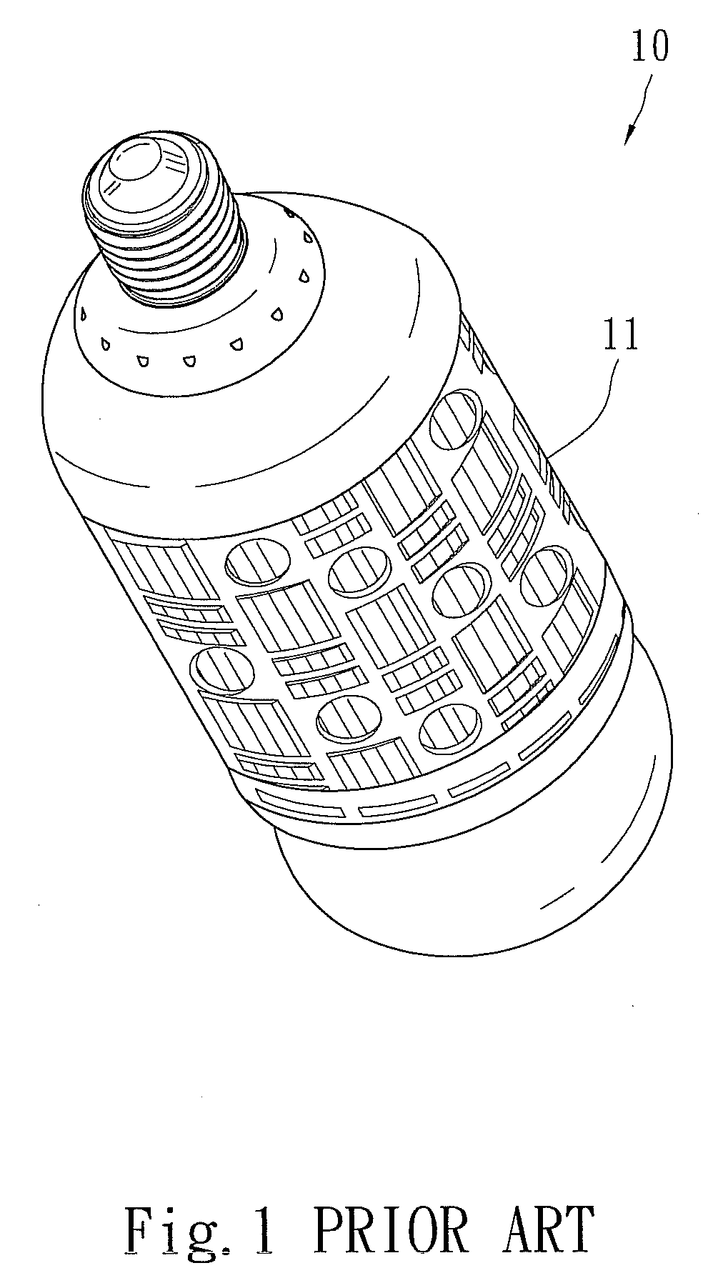
Although the protection shell 11 can be held by the consumer as replacing the LED lamp 10, it also encapsulate the high temperature therein and cause a worse heat dispersing, thereby the LED lamp is easily damaged and the life time thereof is short.
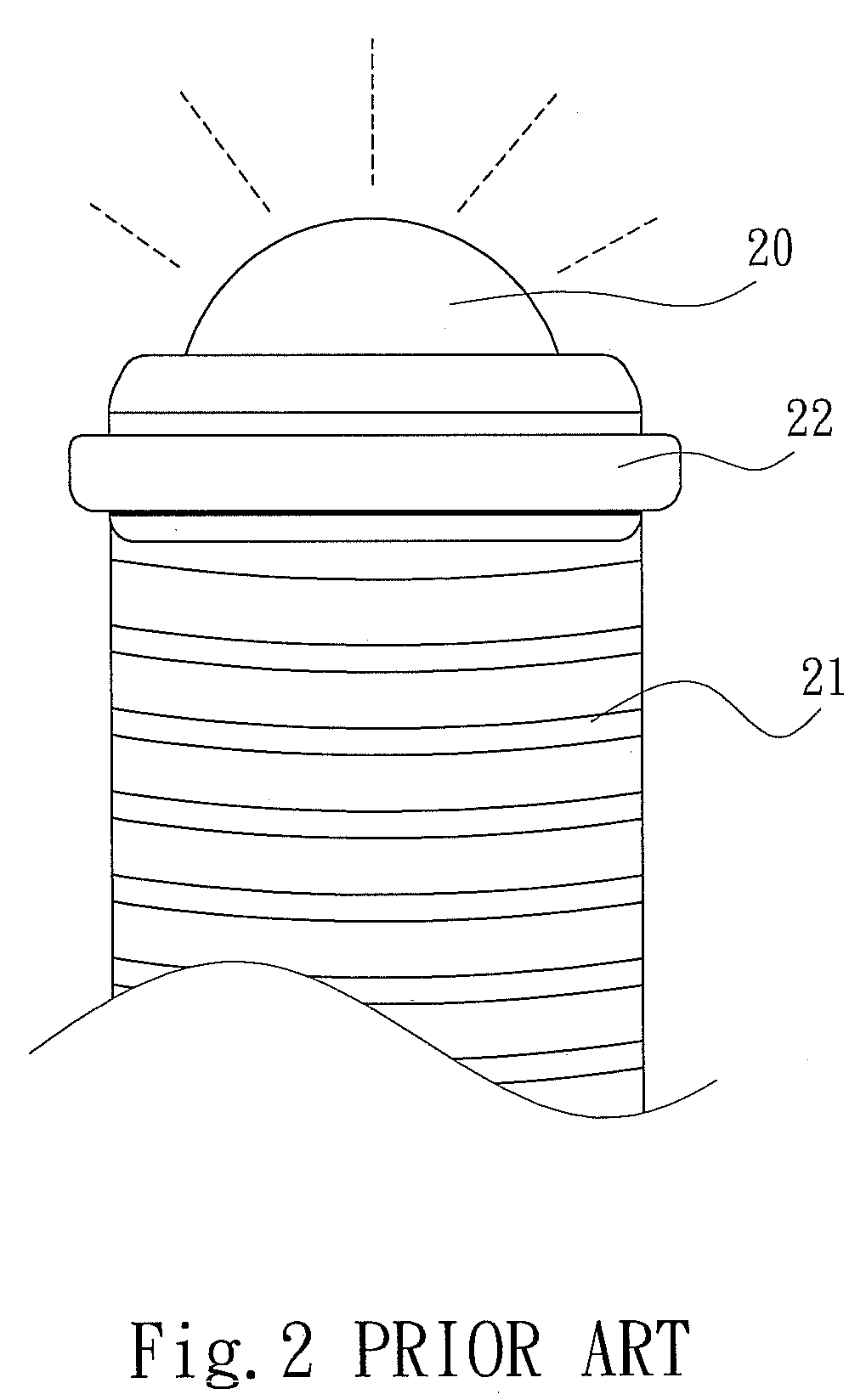
However, after heating a period of time, a bake effect might appear to all heat sinks 21, so that the contact conduction of the heat sinks 21 are easily saturated, thereby increasing the difficulty to disperse the heat.
Therefore, the life time of LED lamp 20 also might be reduced, so that the heat dispersing is still insufficient.

Method used


Image

  • LED lamp bulb structure
  • LED lamp bulb structure
  • LED lamp bulb structure

Examples


Embodiment Construction

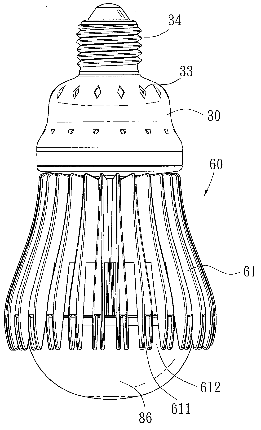
[0015]Please refer to FIG. 3, FIG. 4 and FIG. 6B. The present invention includes a lamp head 30, a lamp controller 40, an upper cover 50, heat dispersing fin set 60, plural heat conducting tubes 70, a lower cover 80, and plural LED lamp sets 90, wherein:

[0016]The lamp head 30 has an inner accommodating space 31 and an engaging space 311 at the bottom thereof for fixedly mounting the lamp controller 40 and the upper cover 50, a screw portion 32 located at the top portion thereof for electrically connecting to a lamp base 34, and plural ventilating holes 33 mounted at an outer edge near the screw portion 32.

[0017]The lamp controller 40 is fixed in the inner accommodating space 31 of the lamp head 30.

[0018]The upper cover 50 is installed in the engaging space 311 of the lamp head 30 and is rejected to the bottom surface of the lamp controller 40, and the upper cover 50 has an inwardly indented chamber 51, which has at least a first through hole 52 and perforation 53 respectively mounte...


PUM


Abstract

A LED lamp bulb structure is disclosed, wherein a lamp controller is installed inside a lamp head and the bottom surface thereof is fixed by an upper cover. At the bottom surface of the upper cover, a heat dispersing fin set, which has at least a heat conducting tube installed therein, and a lower cover are fixed therein. Furthermore, a bulb housing, which has a tray mounted therein, is screwed around the peripheral edge of the lower cover, and at the bottom of the tray, plural LED lamp sets corresponding to plural heat conducting tubes are outwardly extended. Therefore, the heat produced by the LED lamp set can have a heat exchange through plural heat conducting tubes and heat dispersing fin set for achieving a better heat dispersing efficiency and for more effectively dispersing the heat.

Description

FIELD OF THE INVENTION[0001]The present invention is related to a LED lamp bulb structure, and more particularly to a LED lamp bulb structure which call disperse heat more efficiently and more rapidly.BACKGROUND OF THE INVENTION[0002]Owing to the very little energy consumption during operation, LED bulbs have already in place of conventional incandescent lamps in many products, such as decoration lamps, advertisement signs or traffic signs.[0003]However, although the LED lamp 10 can illuminate with very little power supply, the temperature still will become higher when illumination, so that for facilitating replacement, usually, a protection shell 11 (as shown in FIG. 11) is mounted around the LED lamp. Although the protection shell 11 can be held by the consumer as replacing the LED lamp 10, it also encapsulate the high temperature therein and cause a worse heat dispersing, thereby the LED lamp is easily damaged and the life time thereof is short.[0004]Furthermore, another kind of ...

Claims


Application Information

Patent Timeline
IPC IPC(8): F21V29/02
CPCF21V29/004F21Y2101/02F21V3/02F21V29/83F21K9/135F21V29/507F21V29/77F21V23/006F21K9/232F21Y2115/10F21K9/238F21V29/773F21V29/75
Inventor CHANG, KUN-JUNGJUAN, CHING-YUANLIN, KUO-CHUNJUAN, CHING-HUANG
Owner LI HONG TECHNOLOGICAL
Learn More