Combination Venturi Check Valve

a check valve and valve body technology, applied in mechanical equipment, valve types, transportation and packaging, etc., can solve the problems of low suction amount, decrease in the suction rate of the venturi, and inability to suction vacuum

Inactive Publication Date: 2009-12-10
HAYWARD IND INC
View PDF7 Cites 10 Cited by
  • Summary
  • Abstract
  • Description
  • Claims
  • Application Information

AI Technical Summary

Problems solved by technology

A disadvantage to the full-flow set-up of FIG. 1, for example, is that the pressure drop created across the venturi to form a suctioning vacuum also undesirably acts as a backpressure across the fluid circulation system.
A drawback to the bypass set-up of FIG. 2 is

Method used


Image

  • Combination Venturi Check Valve
  • Combination Venturi Check Valve
  • Combination Venturi Check Valve

Examples


Embodiment Construction

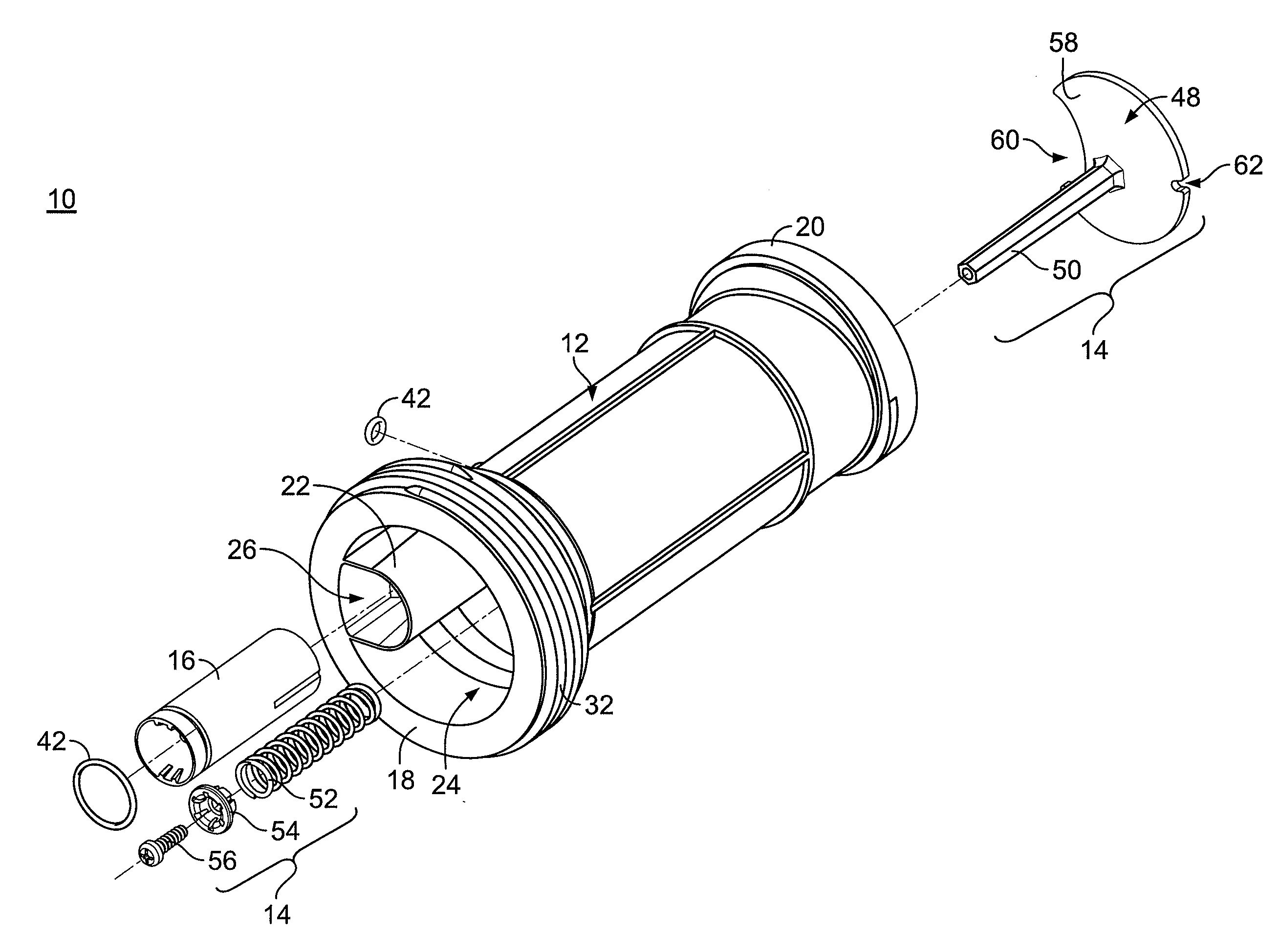
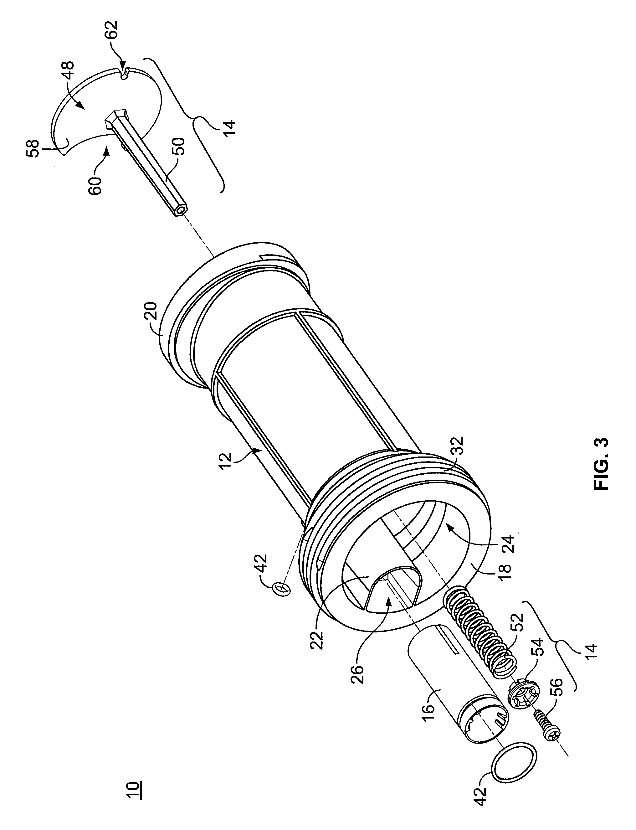
[0016]Referring to FIGS. 3-8B, a combination venturi check valve 10 is shown in accordance with an exemplary embodiment of the invention. The combination venturi check valve 10 includes a housing 12, a valve assembly 14, and a venturi device 16, each of which shall be discussed below with further detail.

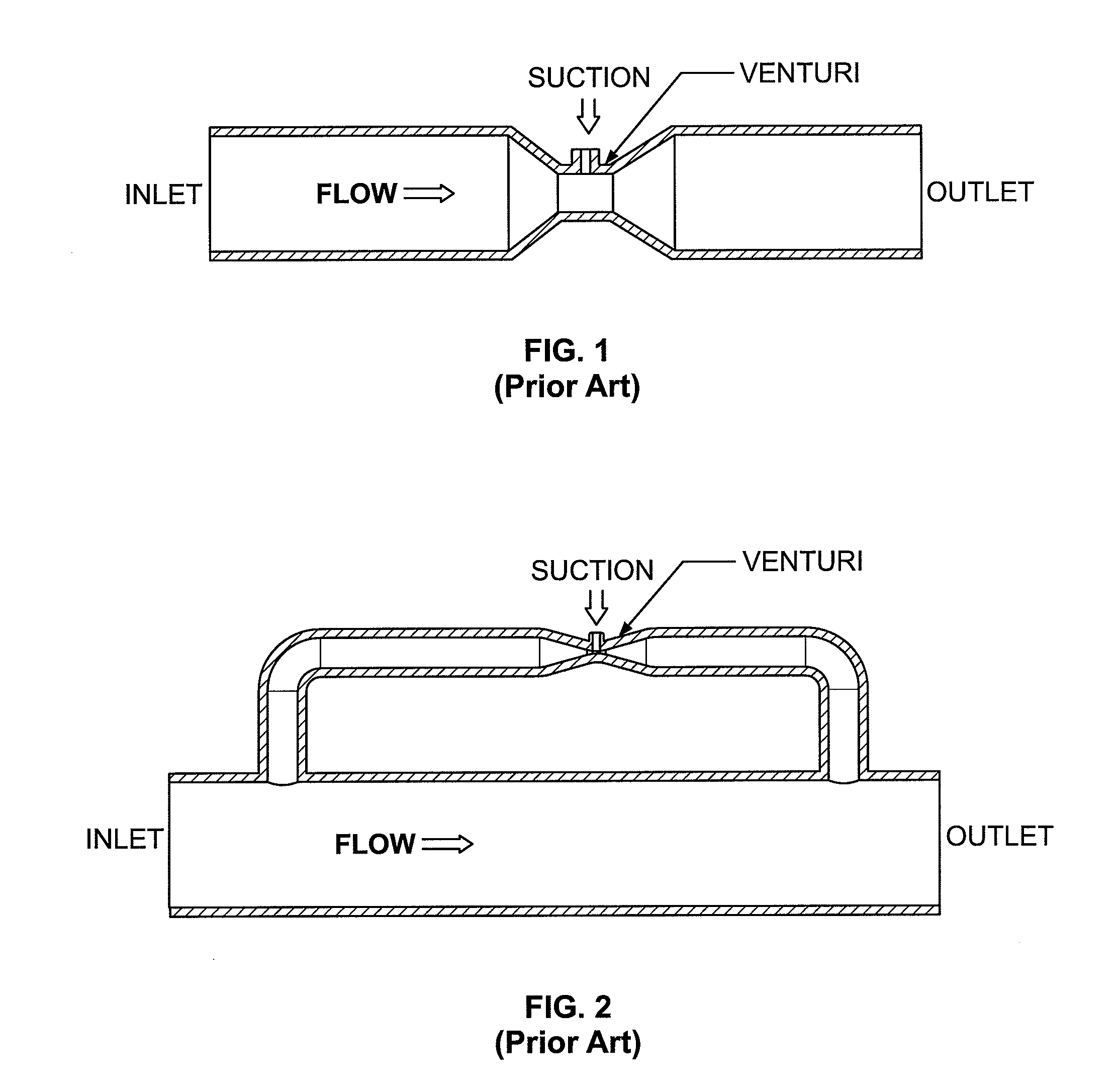
[0017]In the embodiment of FIGS. 3-8B, the combination venturi check valve 10 includes a generally cylindrical pipe housing 12 having a fluid inlet 18, a fluid outlet 20, and a common wall 22 extending therebetween to define a bypass passage 24 and a venturi passage, the latter of which comprises two areas that are referenced herein as a venturi passage inlet side 26 and a venturi passage outlet side 28. The venturi passage inlet side 26 is preferably substantially parallel with respect to the bypass passage 24. A chamber referenced herein as mixing chamber 30 is preferably positioned between the fluid outlet 20 and the passages. Fluid preferably flows from at least one of the passag...


PUM


Abstract

Disclosed herein is a combination venturi check valve for introducing a composition, such as ozone, into the fluid circulation line of a swimming pool, spa, and/or other recreational body of water. The combination venturi check valve preferably includes a fluid inlet, a fluid outlet, a venturi passage for suctioning in the composition, and a bypass passage with a valve enabling compatibility with pumps having different flow rates, for example. In an aspect of the invention, the venturi and bypass passages are inline with the fluid inlet and fluid outlet. In another aspect of the invention, the venturi and bypass passages share a common wall, and/or the housing is modular and/or integrally formed. In yet another aspect of the invention, the valve automatically adjusts the flow rate of fluid through the bypass passage without requiring human intervention.

Description

CROSS-REFERENCE TO RELATED APPLICATIONS[0001]The present application claims the benefit of priority to U.S. Provisional Patent Application No. 61 / 126,643, filed May 6, 2008.FIELD OF THE INVENTION[0002]The present invention relates to a venturi valve for suctioning a composition, such as ozone, into the fluid circulation system of a swimming pool, spa, or other recreational body of water. More specifically, the present invention relates to a valve for a fluid circulation system that includes any one of a plurality of different pumps having disparate pumping rates.BACKGROUND OF THE INVENTION[0003]A venturi is an apparatus commonly used to draw a substance, e.g., a composition, into a fluid by use of a pressure difference. Referring to the prior art “full-flow set-up” of FIG. 1, a venturi can be directly contained within a principal flow path. A disadvantage to the full-flow set-up of FIG. 1, for example, is that the pressure drop created across the venturi to form a suctioning vacuum ...

Claims


Application Information

Patent Timeline
IPC IPC(8): F16K17/34
CPCF16K15/063F16K11/105Y10T137/7754
Inventor CARTER, III, JAMES ANTHONYMACKAY, PETER AULD
Owner HAYWARD IND INC
Why Eureka
Try Eureka