Adjustable leveling mount

Inactive Publication Date: 2009-12-10
RAYTHEON TECH CORP
View PDF23 Cites 26 Cited by
  • Summary
  • Abstract
  • Description
  • Claims
  • Application Information

AI Technical Summary

Benefits of technology

[0008]The vise adjusts to hold a variety of different workpiece configurations. The vise joint orients the adjustable vise with respect to three degrees of freedom in angular motion, providing independent control of the vise's axis angle, attitude angle and rotation angle. The adjustable arm supports the vise joint and the adjustable vise above a work surf

Problems solved by technology

Even the most advanced techniques remain limited, however, by workpiece positioning, which must be as precise and accurate as the manufacturing process itself in order to reach nominal design tolerances and achieve desired product quality goals.
Complex-geometry workpieces pose particular challenges.
Each of these devices has limitations, however, including inadequate precision and accuracy, insufficient degrees of freedom in motion, and the inability to support heavier workpiece configurations without tipping or dropping.
S

Method used


Image

  • Adjustable leveling mount
  • Adjustable leveling mount
  • Adjustable leveling mount

Examples


Example

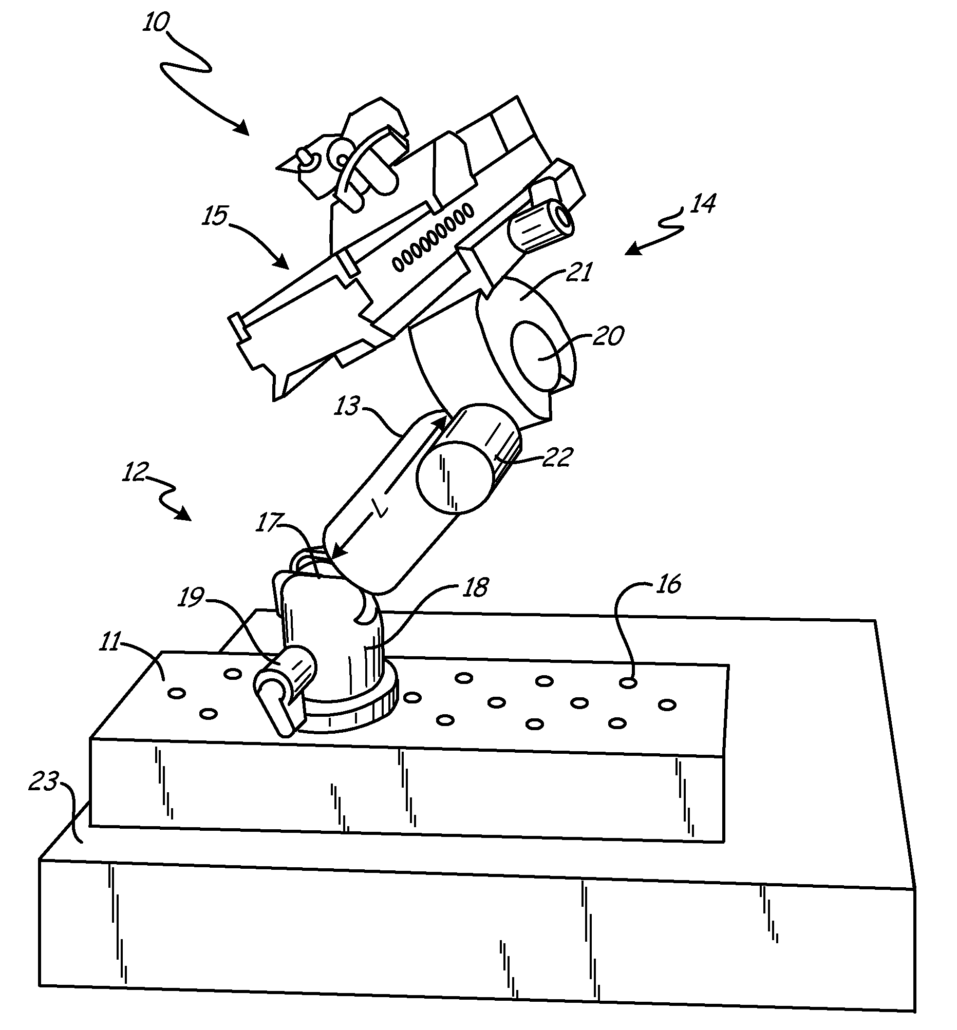
[0013]FIG. 1 is a perspective view of adjustable leveling mount 10. Mount 10 includes a multimember support structure comprising counterweight base 11, arm joint 12, adjustable arm 13 and vise joint 14. The multimember support structure supports adjustable leveling vise 15.

[0014]Counterweight base 11 is comprised of a dense material such as a metal, a dense plastic, a dense resin or other dense filler, or a combination of such materials. Typically, counterweight base 11 comprises mechanical coupling elements such as screw holes 16 for mechanically coupling (attaching) base joint 12 to counterweight base 11.

[0015]Base joint 12 comprises a means for orienting adjustable arm 13 with respect to counterweight base 11. Base joint 12 also supports adjustable arm 13 without tipping or dropping, regardless of the position of adjustable arm 13, vise joint 14 and adjustable vise 15.

[0016]As shown in FIG. 1, base joint 12 comprises a ball-and-socket joint, which in turn comprises ball 17, rotat...


PUM


Abstract

A leveling system for a workpiece comprises a vise for holding the workpiece and a multimember support structure for positioning the vise. The multimember support structure comprises at least two joints and provides at least five independent degrees of freedom in angular motion for positioning the vise and leveling the workpiece.

Description

BACKGROUND OF THE INVENTION[0001]This invention relates generally to adjustable mounting systems, and specifically to an adjustable mount for precision part manufacturing. In particular, the invention concerns an adjustable leveling mount for precision machining, finishing, inspection and measurement of precision manufacture parts and workpieces with complex surface geometry, including vane and blade airfoils for gas turbine engines.[0002]Manufacturing techniques are continuously evolving, particularly in low-tolerance applications for precision manufacture. Even the most advanced techniques remain limited, however, by workpiece positioning, which must be as precise and accurate as the manufacturing process itself in order to reach nominal design tolerances and achieve desired product quality goals.[0003]Complex-geometry workpieces pose particular challenges. In airfoil manufacture for gas turbine engine blades and vanes, for example, individual workpieces must be precisely position...

Claims


Application Information

Patent Timeline
IPC IPC(8): B23Q1/32
CPCB25B1/2484B25B1/22B23Q1/25
Inventor PATEL, JIGARKUMAR
Owner RAYTHEON TECH CORP
Why Eureka
Try Eureka