Automatic paper feed apparatus having improved paper separation device

a paper feeder and automatic technology, applied in the direction of article separation, thin material processing, transportation and packaging, etc., can solve the problems of increasing cost, affecting production efficiency, and affecting production efficiency, so as to improve production efficiency, reduce production costs, and improve production efficiency

Inactive Publication Date: 2007-12-06
ASIA OPTICAL INT LTD
View PDF6 Cites 2 Cited by
  • Summary
  • Abstract
  • Description
  • Claims
  • Application Information

AI Technical Summary

Benefits of technology

[0010]In comparison with the prior art, the paper separation device of the present automatic paper feed apparatus takes the form of a compound gear only consisting of a first paper separation gear and a second paper separation gear. The first and second paper separation gears are rotatably and mutually drivably coupled with each other by the engagement between a projection and a protrusion respectively formed thereon. Due to the linear velocity difference between the paper feed roller and the paper pick-up roller, a clearance is formed between the first and second paper separation gears, whereby successive paper sheets are separated from each other, one by one, by a predetermined interval. By such a design, the present paper separation device has the advantages of easy manufacturing, low cost and adequate precision.

Problems solved by technology

When the paper sheet leaves the paper pickup roller, the paper pickup roller will stop rotating because loss of driving power from the paper feed roller.
However, such a combination complicates the manufacturing, increases the cost, and also occupies a large transverse space in an automatic paper feed apparatus.

Method used


Image

  • Automatic paper feed apparatus having improved paper separation device
  • Automatic paper feed apparatus having improved paper separation device
  • Automatic paper feed apparatus having improved paper separation device

Examples


Embodiment Construction

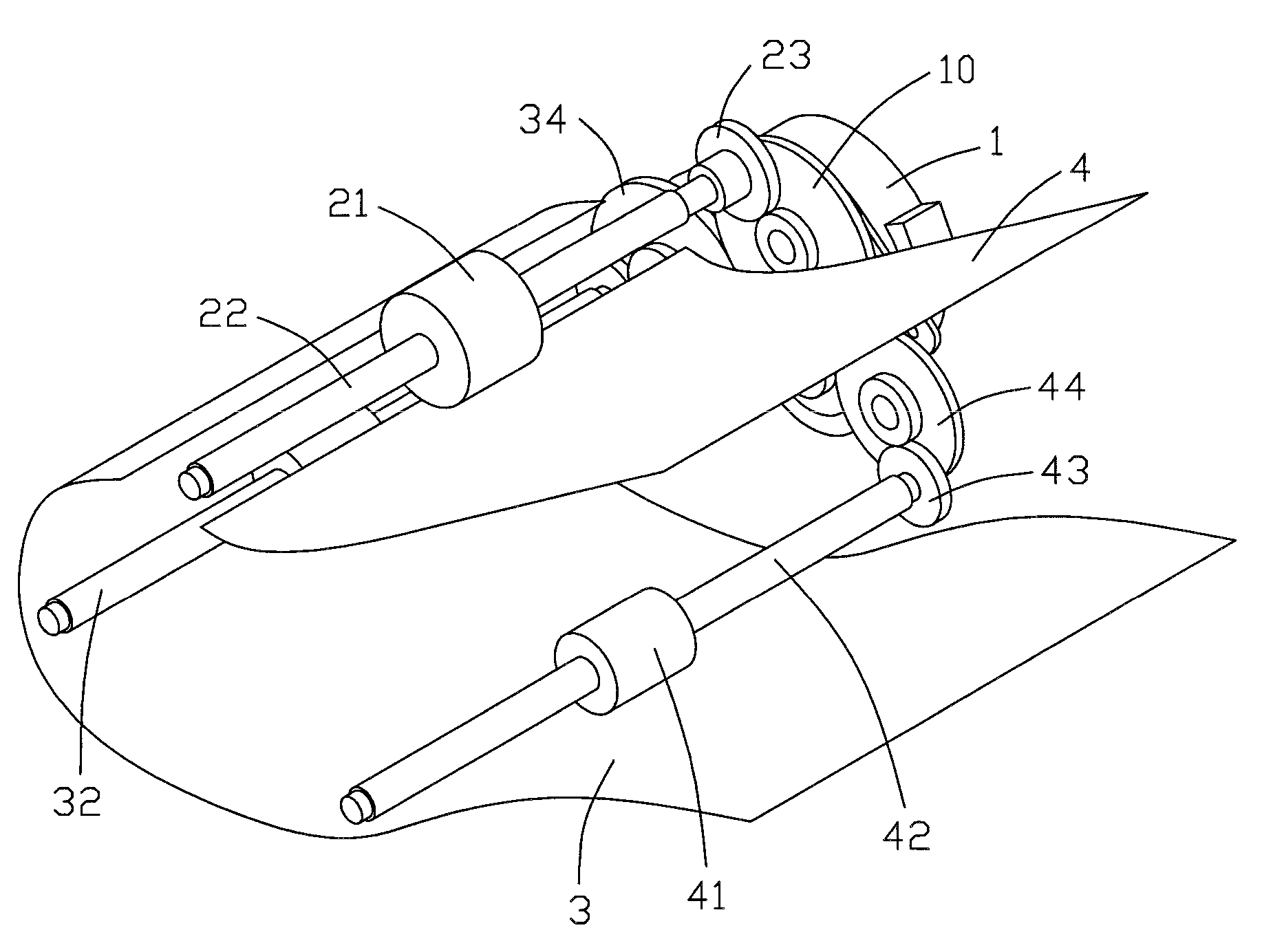
[0016]To simplify description, the following detailed description of the present invention is only directed to the structures of a paper separation device, a paper pickup roller, a paper feed roller and a paper exit roller of an automatic paper feed apparatus constructed in accordance with the present invention and the relationship therebetween. Since the other constituent components of the automatic paper feed apparatus are substantially the same as those of the prior art and do not form an essential part of the inventive concept of the present invention, a detailed description thereof is thus omitted hereinafter.

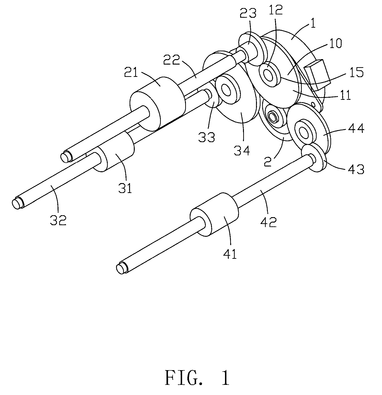
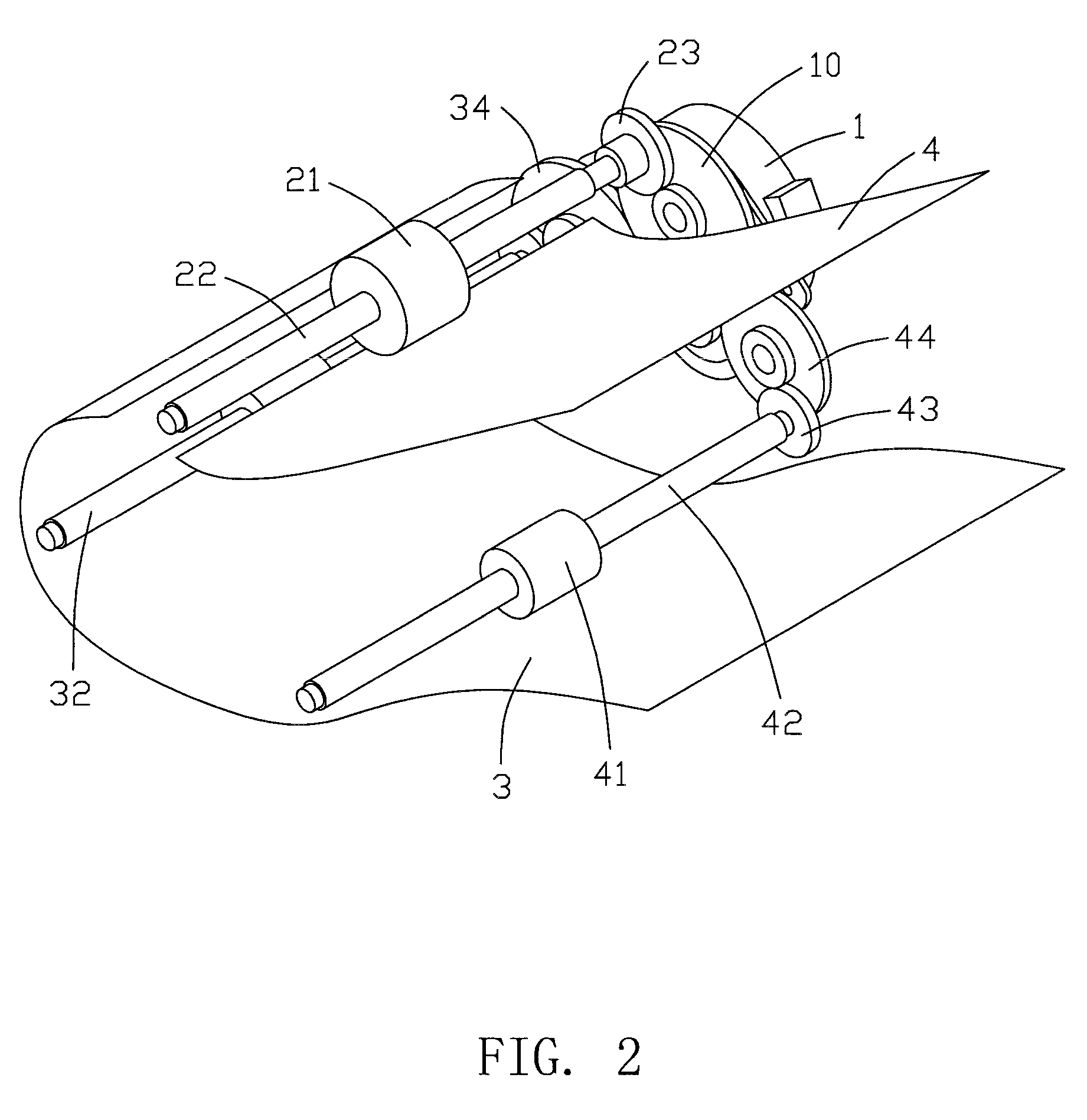
[0017]Referring to FIG. 1, an automatic paper feed apparatus in accordance with the present invention includes a power source 1, a paper transmission device and a paper separation device 10.

[0018]The power source 1 is in the form of a motor. The motor 1 drives a motor gear (not shown), and the motor gear then drives a driven gear 2 for driving other components of the prese...


PUM


Abstract

An automatic paper feed apparatus includes a paper pickup roller (21), a paper feed roller (31) and a paper separation device (10). The paper separation device is a compound gear consisting of a first paper separation gear (11) and a second paper separation gear (12). The first and second paper separation gears are rotatably and mutually drivably coupled with each other by the engagement between a projection (13) and a protrusion (14) respectively formed thereon. The paper pickup roller and the paper feed roller are respectively actuated to rotate by the second and first paper separation gears through a paper pickup gear mechanism (23) and a paper feed gear mechanism (33, 34) each mounted on a same shaft and engaged therebetween. At the initial stage, the first paper separation gear drives the second paper separation gear to rotate, and thus the paper pickup roller and the paper feed roller are respectively actuated to rotate by the second and first paper separation gears. By then making the linear velocity of the paper feed roller to be higher than that of the paper pickup roller, a predetermined angular clearance is formed between the projection and protrusion of are separated from each other, one by one, by a predetermined interval.

Description

BACKGROUND OF THE INVENTION[0001]1. Field of the Invention[0002]The present invention relates to an automatic paper feed apparatus, and particularly to an automatic paper feed apparatus having an improved paper separation device.[0003]2. Description of Prior Art[0004]An automatic paper feed apparatus generally includes a paper pickup roller for picking up one by one the paper sheets stored in a paper cassette from the uppermost one, and a paper feed roller for feeding the picked-up sheet into the automatic paper feed apparatus. The main concern for the automatic paper feed apparatus is how to automatically and reliably separate paper sheets one by one. Various conventional paper separation technologies have been proposed, within which utilizing the linear velocity difference between the paper pickup roller and the paper feed roller to accomplish the paper separation purpose is a cheap and reliable one.[0005]Taiwan Patent No. 258086 discloses an automatic paper separation device in t...

Claims


Application Information

Patent Timeline
Patent Type & Authority Applications(United States)
IPC IPC(8): B65H5/00
CPCB65H3/0669B65H2403/42B65H5/06
Inventor LIN, HSIEN-CHI
Owner ASIA OPTICAL INT LTD
Why Eureka
Try Eureka