Sealing gland system

Active Publication Date: 2009-12-10
CHANNELL COMML CORP
View PDF29 Cites 52 Cited by
  • Summary
  • Abstract
  • Description
  • Claims
  • Application Information

AI Technical Summary

Benefits of technology

[0012]The above aspects of this invention are more fully exp...

Problems solved by technology

In the past, due to difficulties including lack of infrastructure development within cities, and the complexity and expensive of fiber optic system, fiber-optic commu...

Method used


Image

  • Sealing gland system
  • Sealing gland system
  • Sealing gland system

Examples


Embodiment Construction

[0023]With reference to the drawings, a sealing gland system for a telecommunication terminal system according to the present invention will now be described.

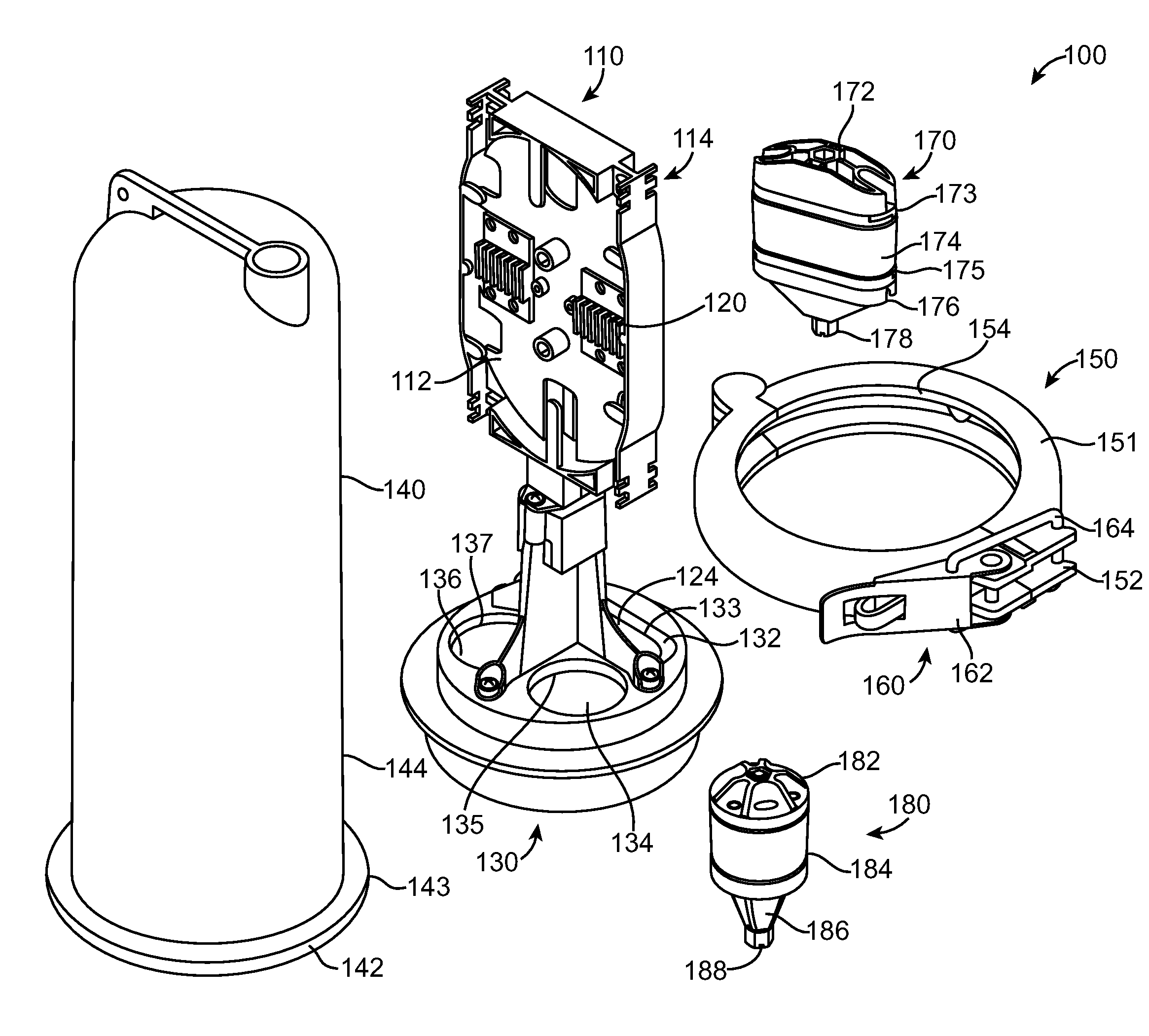
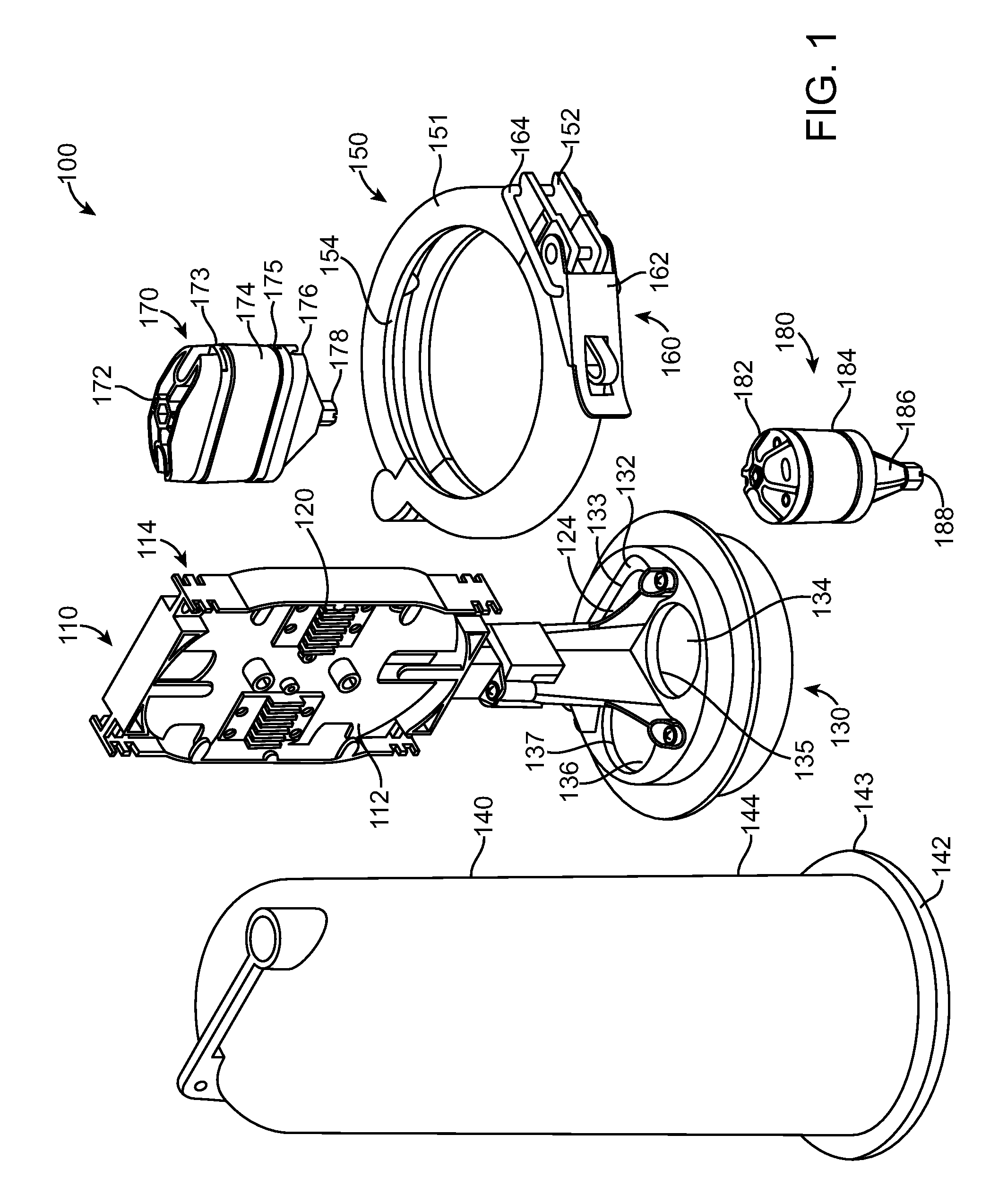
[0024]FIG. 1 is a perspective view of a telecommunication terminal system 100 in accordance with an embodiment. As shown in FIG. 1, in accordance with an exemplary embodiment, the telecommunication terminal system 100 (e.g., bracket mounted terminal or “BMT”) includes an organizer or terminal block 110, and at least one splice or fiber tray 120, which is attachable to a base unit 130. The system 100 also includes a housing or dome enclosure 140, a lockable sealing unit 150 having a bracket or hinge clamp 160, which seals the base unit 130 to the housing 140, and at least one sealing gland 170, 180. In accordance with an exemplary embodiment, the telecommunication terminal system 100 is configured to accommodate various organizers or terminal blocks 110 and base units 130, such as a bracket mounted terminal system (BMT) as manuf...


PUM


Abstract

A sealing gland system having an upper half, a lower half, and a sealing material positioned between the upper and lower halves. Each of the upper and lower halves and the sealing material has at least one opening extending therethrough, and wherein the sealing material forms a seal around at least one cable extending through the sealing material upon compression thereof.

Description

FIELD OF THE INVENTION[0001]This invention relates to a sealing gland system for telecommunication housings, enclosures, terminals, and more particularly to a sealing gland system for bracket mounted terminals (BMT) for use in the telecommunications industry.BACKGROUND OF INVENTION[0002]Telecommunication terminals (or terminal blocks) are typically used in the telecommunications industry to connect multiple wire pairs, for example, to connect telephone service wires to telephone company distribution cables. Such terminal blocks typically connect from 2 to 50 individual service wire pairs to the distribution cable that may have several thousand-wire pairs. Generally, the terminal block is spliced to the distribution cable through a splicing cable or stub cable that forms part of the telecommunication terminal or terminal block. The customer service wires are then connected to the telecommunication terminal or terminal block through some type of terminal, which, ideally, enables the s...

Claims


Application Information

Patent Timeline
IPC IPC(8): G02B6/00F16L21/05
CPCH02G15/013
Inventor SHIMIRAK, GERALD L.SHEALS, DEREC
Owner CHANNELL COMML CORP
Why Eureka
Try Eureka