Reflective optical circulator

a circulator and optical technology, applied in the field of optical circulators, can solve the problems of large size difficult to implement the optical circulator having multiple ports, and inability to meet the requirements of the optical circulator, so as to prevent the non-uniformity of the insertion loss of each reciprocating optical path in the optical circulator, stabilize the insertion loss, and prevent the occurrence of pdl

a circulator and optical technology, applied in the field of optical circulators, can solve the problems of large size difficult to implement the optical circulator having multiple ports, and inability to meet the requirements of the optical circulator, so as to prevent the non-uniformity of the insertion loss of each reciprocating optical path in the optical circulator, stabilize the insertion loss, and prevent the occurrence of pdl

US20090304392A1Inactive Publication Date: 2009-12-10NAMIKI PRECISION JEWEL CO LTD

Image

  • Reflective optical circulator
  • Reflective optical circulator
  • Reflective optical circulator

Examples


Embodiment Construction

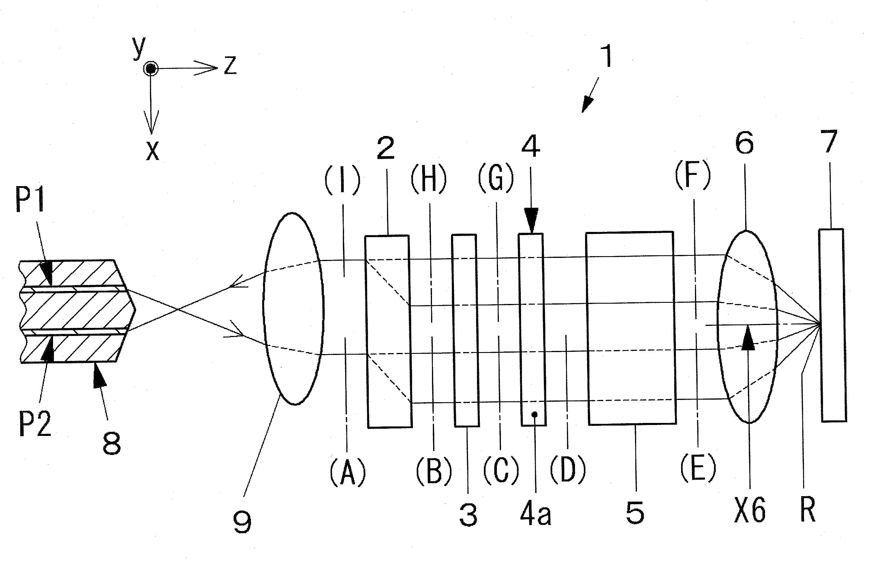
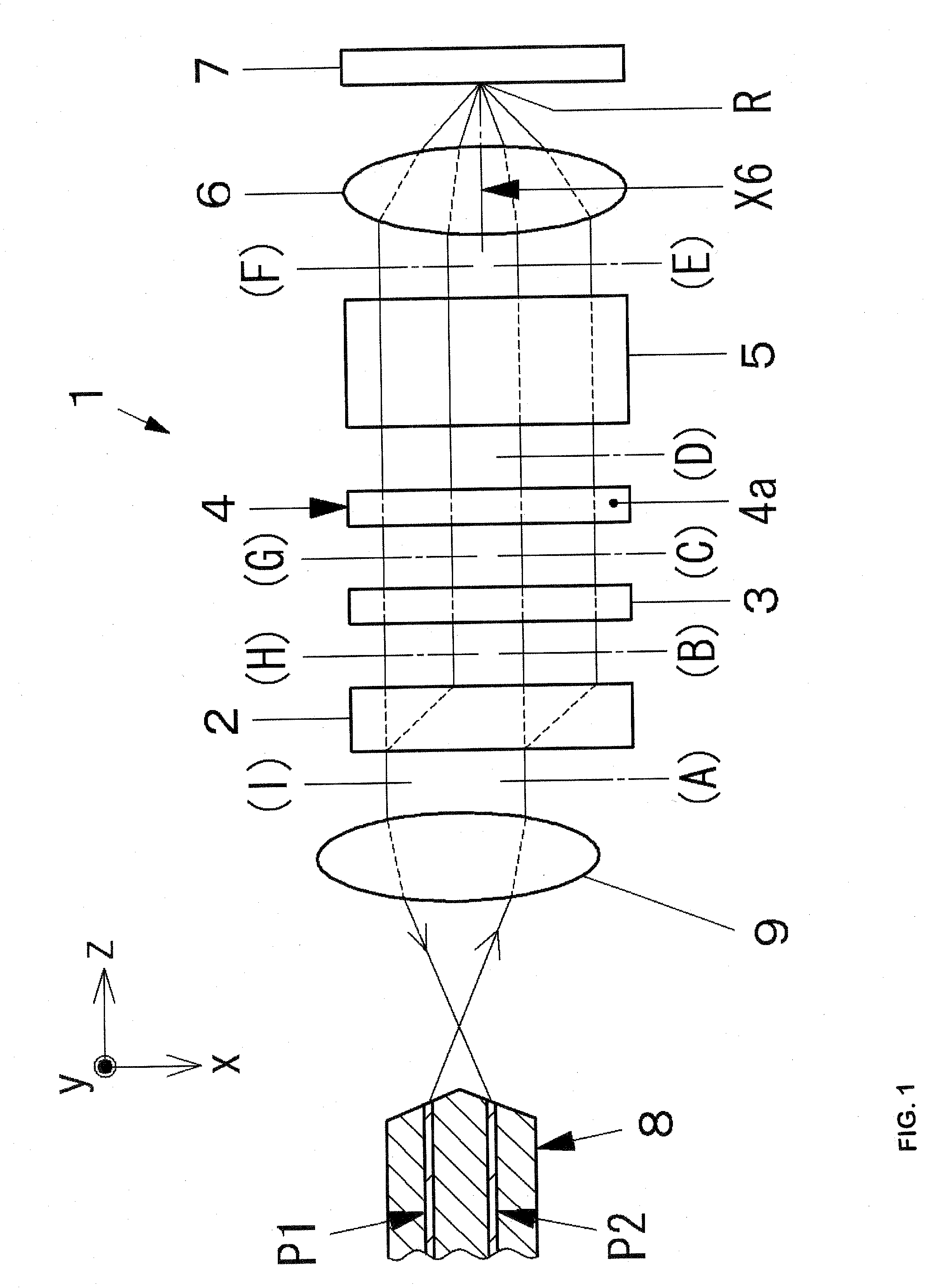
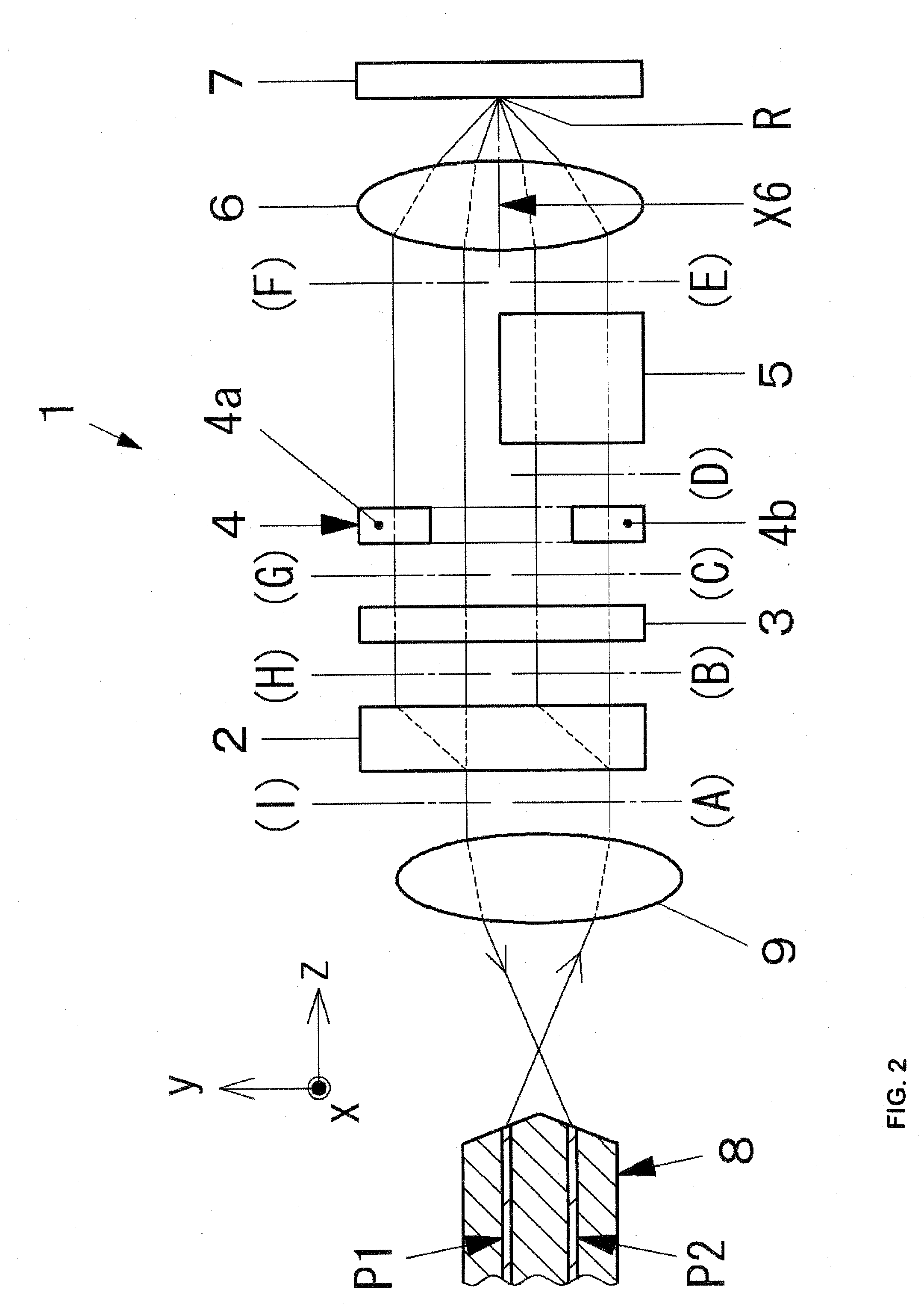
[0057]Hereinafter, best mode embodiment of optical circulators according to the present invention will be described in detail with reference to FIGS. 1 to 14. In each figure, x-axis to z-axis correspond to those of each figure. In FIGS. 1 and 2, the light propagating direction is denoted by the z-axis, horizontal and vertical directions in a plane perpendicular to the z-axis are denoted by x-axis and y-axis, respectively. FIGS. 1 and 2 illustrate the constitution and layout of each of optical elements from the light incidence / emission unit 8 to the reflector 7 of the optical circulator 1. Optical paths where the light passes through internal portions of each of the optical elements are indicated by dashed lines, and the other optical paths are denoted by solid lines.

[0058]As shown in FIGS. 1 and 2, the optical circulator 1 according to the present invention includes an optical element unit having a first polarization separating element 2 (hereinafter, referred to as a polarization s...


PUM


Abstract

Provided is a reflective optical circulator capable of improving characteristics by preventing the occurrence of PDL and non-uniformity of insertion losses of reciprocating optical paths. The reflective optical circulator includes: an optical element unit having a first polarization separating element, a 45° non-reciprocal polarization plane rotating element, a phase element for rotating a polarization plane of an incident light by 90°, and a second polarization separating element; a light incidence / emission unit; a lens; and a reflector. All waveguides are disposed at an equivalent distance from a central point, and a shift amount of an extraordinary ray in the second polarization separating element is set to be larger than a shift amount of an extraordinary ray in the first polarization separating element. In addition, the phase element is constructed with two phase optical elements, and only one polarization component is allowed to transmit through the two phase optical elements. In addition, a size of the second polarization separating element is set so that light transmits through only one path of reciprocating optical paths, and the two polarization components are reflected by the reflector with a point symmetry, and a light in the forward direction is set to be incident to the second polarization separating element before being reflected.

Description

TECHNICAL FIELD [0001]The present invention relates to an optical circulator used for an optical communication system, optical measurement or the like, and more particularly, to a reflective optical circulator having a reflector for forming a reciprocating optical path by reflecting light.BACKGROUND ART [0002]An optical circulator is a non-reciprocal optical device having important roles in an optical communication system, optical measurement or the like. The optical circulator has at least three ports. For example, in case of an optical circulator having three ports indicated by reference numerals 1, 2, and 3, in a forward direction of 1→2, 2→3, 3→1, light is propagated with low loss, and in a backward direction of 3→2, 2→1, 1→3, light is propagated with high loss.[0003]However, since the optical circulator has a structure where light is propagated from one port to other opposite ports in the propagation direction, there is a problem that the number of optical elements is increased...

Claims


Application Information

Patent Timeline
10 Dec 2009
Publication
US20090304392A1
IPC
H04B10/00
CPC
G02B6/2746; G02F1/093; G02B27/286; G02B6/2793
Inventors
KONNO, YOSHIHIRO; SASAKI, MASARU