Support plate, carrier device, releasing device, and releasing method

a technology of releasing device and support plate, which is applied in the direction of grinding drive, grinding machine components, manufacturing tools, etc., can solve the problems of unable to prevent stress from being applied to a wafer, unable to pull on the support plate to release the wafer from the wafer, and difficult for this device to suction and hold a wafer without stressing the wafer

Inactive Publication Date: 2009-12-10
TOKYO OHKA KOGYO CO LTD
View PDF10 Cites 45 Cited by
  • Summary
  • Abstract
  • Description
  • Claims
  • Application Information

AI Technical Summary

Benefits of technology

[0009]It is an object of the present invention to provide a support plate, a carrier device, a releasing device, and a releasing method by which stress applied to a wafer when the wafer and a support plate with through holes are released from each other can be reduced.

Problems solved by technology

However, as wafers have become thinner in recent years, it has become difficult for this device to suction and hold wafers without applying stress to the wafers.
However, wafers are thinned to between several tens of micrometers and several hundred micrometers as described above, and it is impossible to prevent stress from being applied to a wafer when the wafer is pulled upon to be released from a support plate.
However, when it is attempted to suction and hold the bottom surface (surface opposite to the surface contacting the wafer) of the support plate, through holes in the support plate make it impossible to pull on the support plate to release it from the wafer.

Method used


Image

  • Support plate, carrier device, releasing device, and releasing method
  • Support plate, carrier device, releasing device, and releasing method
  • Support plate, carrier device, releasing device, and releasing method

Examples


Embodiment Construction

[0040]Hereinafter, a support plate, a carrier device, a releasing device, and a releasing method according to the present invention will be explained by referring to the drawings.

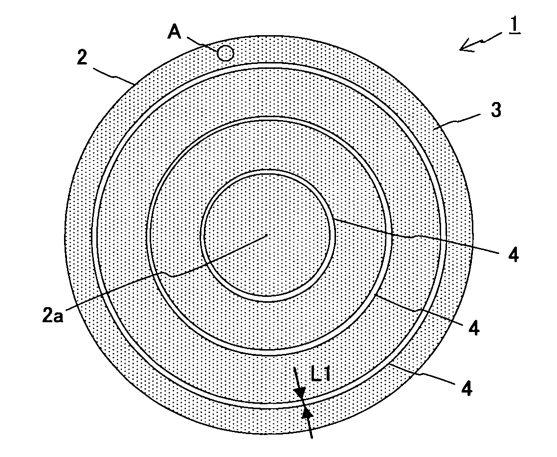
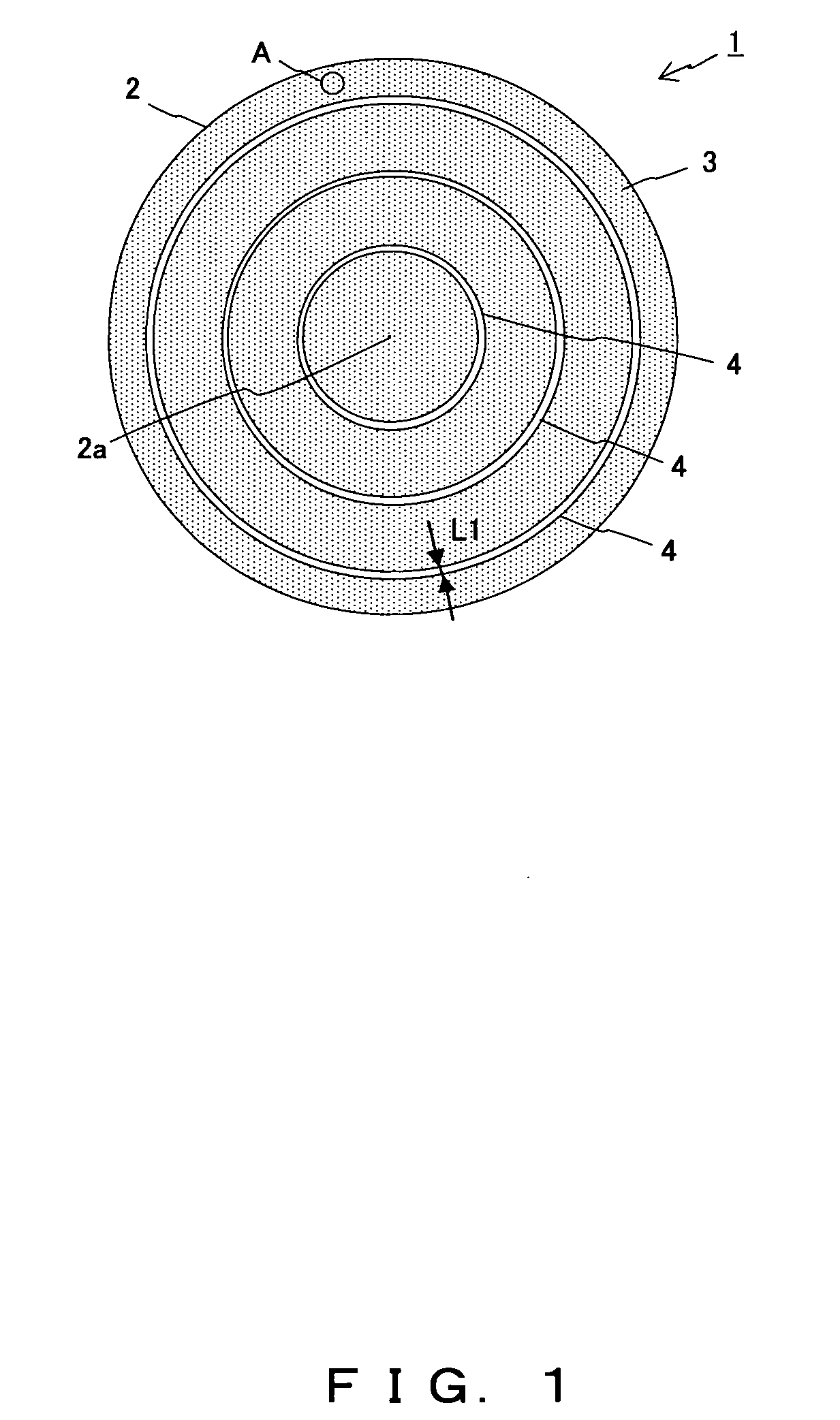
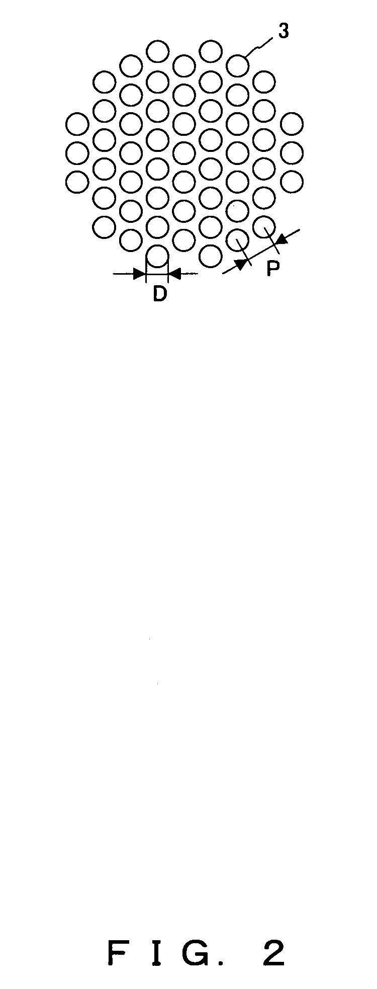
[0041]FIG. 1 is a plan view showing a support plate according to an embodiment. FIG. 2 is an enlarged view showing portion A in FIG. 1.

[0042]A support plate 1 shown in FIG. 1 supports a wafer to be thinned through, for example, a grinding process. The support plate 1 supports, via a bonding portion made of an adhesive agent, tape, etc., a wafer on its supporting surface (not shown in FIG. 1) disposed on the surface opposite to a bottom surface 2 shown in FIG. 1.

[0043]A plurality of through holes 3 (FIG. 2) are formed through the support plate 1. The through holes 3 pierce the support plate 1 from the supporting surface to the bottom surface 2 (in the thickness direction). Three belt-shaped flat portions 4 on which the through holes 3 are not formed are formed on the bottom surface 2. The respective flat por...


PUM

PropertyMeasurementUnit
widthaaaaaaaaaa
widthaaaaaaaaaa
diameteraaaaaaaaaa

Abstract

A support plate for supporting a wafer includes a plurality of through holes piercing the support plate in the thickness direction, and a belt-shaped or island-like flat portion on which the plurality of through holes are not formed.

Description

TECHNICAL FIELD[0001]The present invention relates to a support plate for supporting a semiconductor wafer (referred to as a wafer hereinafter) used for manufacturing semiconductor chips, and to a carrier device, a releasing device, and a releasing method.BACKGROUND ART[0002]Semiconductor chips used in portable electronic devices such as IC cards, mobile phones, digital cameras, etc. are manufactured by dividing a wafer into rectangular or square chips. Wafers are made by forming a circuit pattern on, for example, silicon.[0003]In a process of manufacturing wafers, a circuit pattern is formed on a wafer, and thereafter a support plate is adhered to the circuit-formation surface of the wafer by means of bonding or the like. Next, the bottom surface (the surface opposite to the circuit-formation surface) of the wafer is thinned by grinding, polishing, etc. After the wafer has been thinned to a desired thickness, the support plate and the wafer are released from each other.[0004]There ...

Claims


Application Information

Patent Timeline
Patent Type & Authority Applications(United States)
IPC IPC(8): H01L21/683H01L21/02B25B11/00B29C43/50
CPCH01L21/6875H01L21/6838
Inventor NAKAMURA, AKIHIROMIYANARI, ATSUSHIINAO, YOSHIHIRO
Owner TOKYO OHKA KOGYO CO LTD
Why Eureka
Try Eureka