Alignment Angle Method and Apparatus for a Display

a technology of alignment angle and display, which is applied in the manufacture of electrode systems, lighting support devices, ceilings, etc., can solve the problems of large errors in overall pixel alignment accuracy, user's typical acceptance of a reduced accuracy, and time-consuming and complex process of accurate positioning of tiles

Active Publication Date: 2009-12-17
BARCO INC
View PDF11 Cites 71 Cited by
  • Summary
  • Abstract
  • Description
  • Claims
  • Application Information

AI Technical Summary

Problems solved by technology

Accurate positioning of the tiles may be a time consuming and complex process involving skilled personnel.
Small errors in the positioning of the pixels within tiles and tiles within a display can be cumulative and may lead to large errors in overall pixel alignment accuracy.
The goal of simultaneous strength, rigidity, and accuracy is one that is not achieved in prior art systems and the user typically has to accept a reduced accuracy in order to achieve the required strength.

Method used


Image

  • Alignment Angle Method and Apparatus for a Display
  • Alignment Angle Method and Apparatus for a Display
  • Alignment Angle Method and Apparatus for a Display

Examples


Embodiment Construction

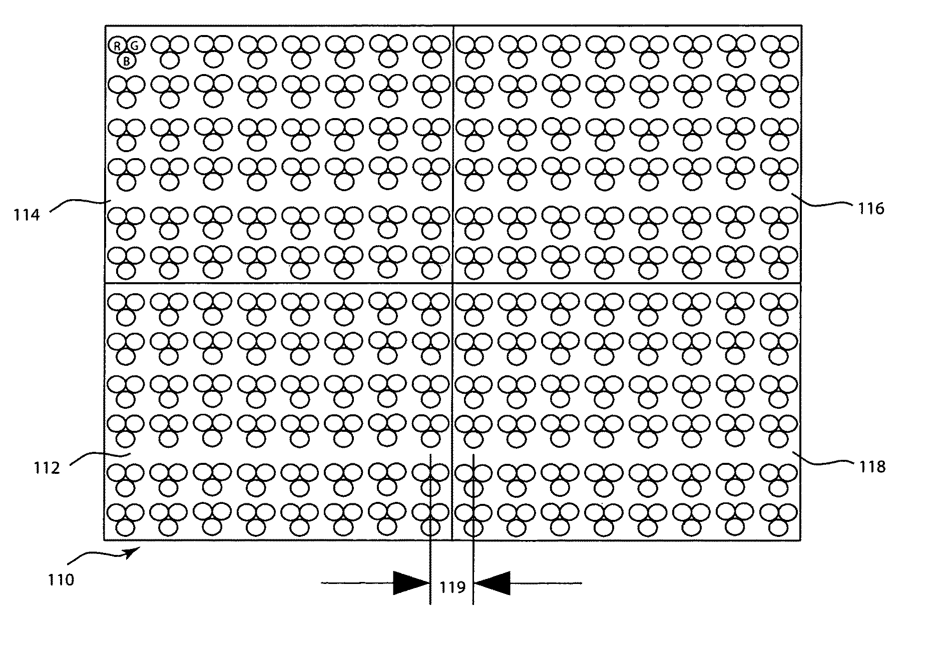
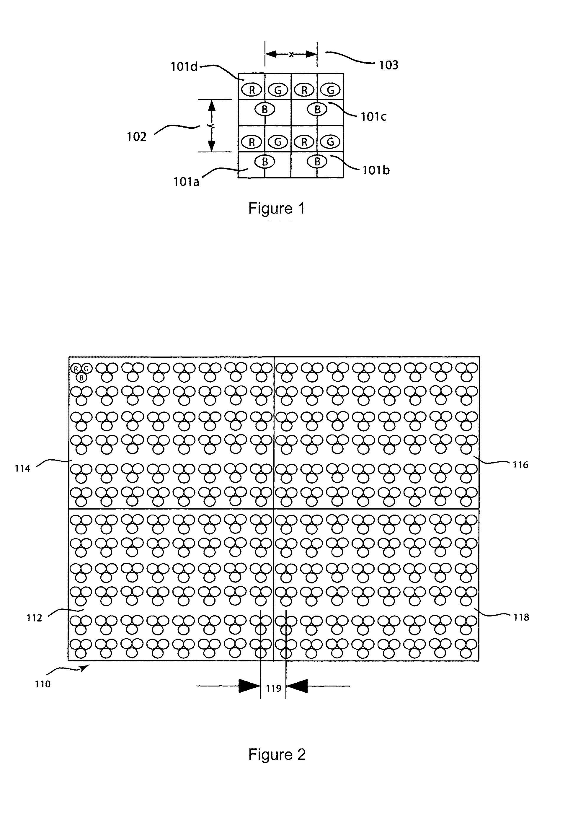
[0057]FIG. 1 shows four pixels in a video display. Each pixel 101a, 101b, 101c, and 101d may be constructed from 3 LEDs: red (R), green (G), and blue (B). The distance 103 and 102 between the center of a pixel 101 and the horizontally or vertically adjacent pixels is referred to as the pixel pitch. The x-axis pixel pitch 103 may be the same as the y-axis pixel pitch 102.

[0058]In a large display with a large number of pixels it is desirable that the pixel pitch is controlled within tight tolerances. Errors in the pixel pitch across the display may be apparent to the viewer and adversely affect the image quality.

[0059]Some more details on video display products can be found in U.S. patent application Ser. Nos. 12 / 415,627, filed Mar. 31, 2009; 12 / 484,200, 12 / 484,201, 12 / 484,202, 12 / 484,205, and 12 / 484,206, all filed Jun. 13, 2009; and U.S. provisional patent applications 61 / 072,597, filed Mar. 31, 2008, and 61 / 170,887, filed Apr. 20, 2009, which are incorporated by reference.

[0060]FIG....


PUM

PropertyMeasurementUnit
lengthaaaaaaaaaa
lengthaaaaaaaaaa
thicknessaaaaaaaaaa

Abstract

A light-emitting display system has an alignment mechanism to align or angle light-emitting tiles of the display. A first tile connects to a second tile by joining a first clamp portion on the first tile with a second clamp portion on the second tile. In an implementation, the alignment mechanism includes a replaceable angle adjustment insert that is inserted into at least one of the clamp portions, such as the first clamp portion. When the first and second clamp portions are joined, a surface of the second clamp portion presses against the insert and a desired angle between the first and second tile is formed. The insert can have any angle so that any desired angle can be formed between the first and second tiles.

Description

CROSS-REFERENCE TO RELATED APPLICATIONS[0001]This patent application is a continuation-in-part of U.S. patent application Ser. No. 12 / 484,203, filed Jun. 13, 2009, and claims the benefit of U.S. provisional patent applications 61 / 061,338; 61 / 061,347; 61 / 061,353; 61 / 061,358; 61 / 061,365; and 61 / 061,369, all filed Jun. 13, 2008, which are incorporated by reference along with all other references cited in this application.BACKGROUND OF THE INVENTION[0002]This disclosure generally relates to display units and particularly to a display unit including groups of light-emitting elements mounted to a support structure such that the display may be configured in nonplanar configurations while retaining both strength and positional accuracy. The invention discloses improvements in the structure and manufacture of such systems.[0003]Display units for entertainment, architectural, and advertising purposes have commonly been constructed of numbers of light-emitting elements such as LEDs or incandes...

Claims


Application Information

Patent Timeline
Patent Type & Authority Applications(United States)
IPC IPC(8): H01J1/62H01J9/20
CPCG09F9/33G09F15/0068G09F9/3026G09F13/14Y10T29/49826Y10T29/49959Y10T403/72Y10T403/7094Y10T403/725G09F13/00F16B2200/30F16B2200/65G09F13/04F21V21/14F21Y2113/13F21Y2115/10F21V21/005
Inventor PATTERSON, MARCUS ROBERTELLIOTT, GRANT ARTHUR JOHN
Owner BARCO INC
Why Eureka
Try Eureka