Heating system

a technology of heating system and heat exchanger, which is applied in the field of heating system, can solve the problems of consuming more power than it generated, many domestic wind turbine installations are simply not efficient, etc., and achieve the effect of aggressive start of space heating system

Inactive Publication Date: 2009-12-24
ZENEX TECH
View PDF45 Cites 13 Cited by
  • Summary
  • Abstract
  • Description
  • Claims
  • Application Information

AI Technical Summary

Benefits of technology

[0014]It is thus possible to use heat held in a heat stor...

Problems solved by technology

Many domestic wind turbine installations are simply not efficient.
Furthermore because it needed to be connected to...

Method used


Image

  • Heating system
  • Heating system
  • Heating system

Examples


Embodiment Construction

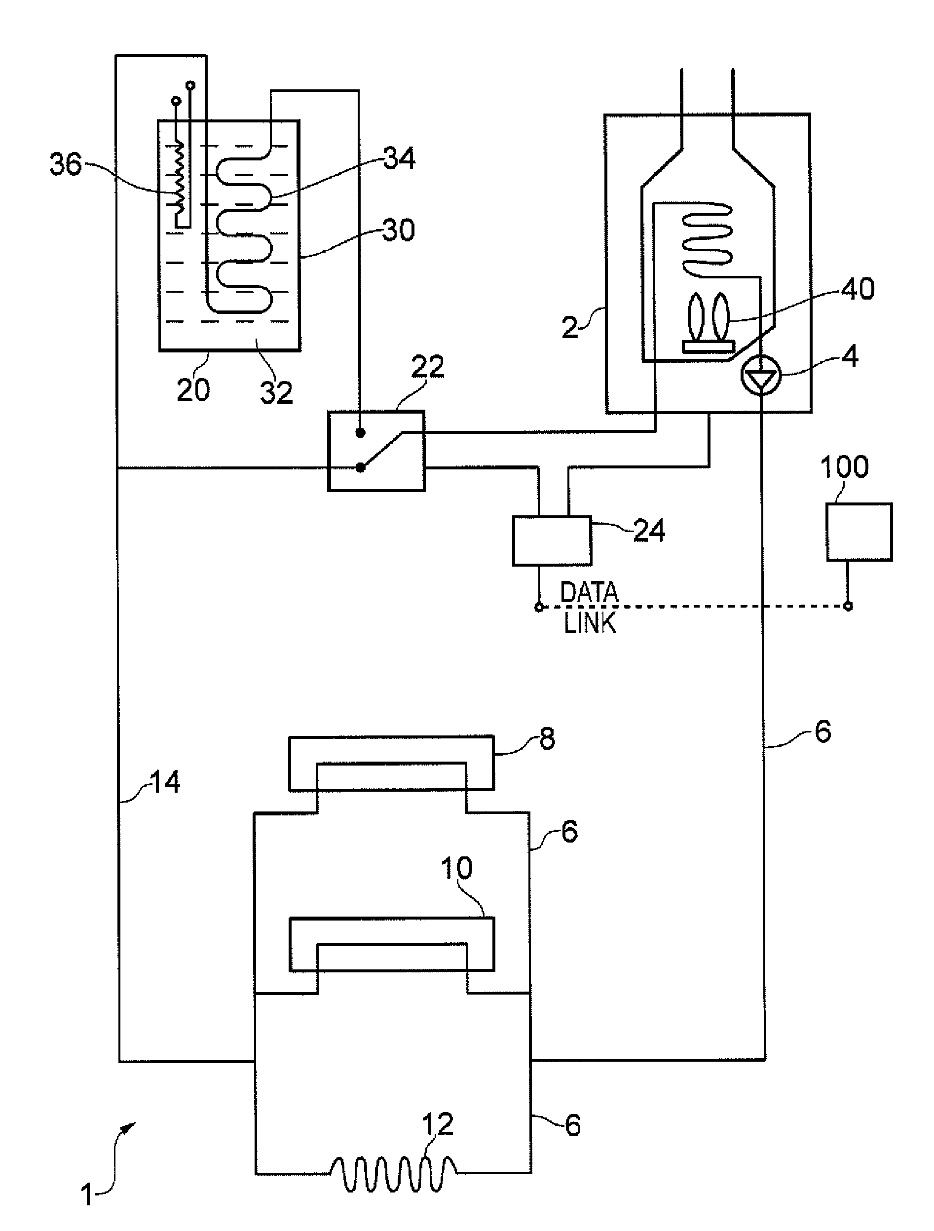
[0022]FIG. 1 schematically illustrates a heating system 1 constituting an embodiment of the present invention. The heating system comprises a heater 2, which could be any heating source but typically comprises a fossil fuel boiler. The fossil fuel may be coal, oil or gas.

[0023]The boiler heats a fluid, which is almost invariably water, and uses a pump 4 to circulate the water through a delivery network 6 to at least one space heater 8, 10, 12. Space heaters 8 and 10 may, for example, be radiators which are common in European homes. A further space heater 12 may be an under floor loop for providing under floor heating.

[0024]Water is cooled as it passes through the space heaters and gives its heat up to the enclosed space within a building. The water then flows along a return path 14 of the delivery network back to the heater 2 for reheating. The system described to this part is a conventional space heating arrangement.

[0025]The inventor realized that a space heating system is usually...


PUM


Abstract

A heating system in which a warmed fluid is circulated through a delivery network space heaters to provide space heating, further comprising a thermal store and means arranged to circulate the warmed fluid through the thermal store during a heating shut down sequence to recover heat from the warmed fluid.

Description

FIELD OF THE INVENTION[0001]The present invention relates to a heating system where space heating is performed by passing a warm liquid through heat exchange devices.BACKGROUND OF THE INVENTION[0002]It is known to provide space heating by heating a fluid using a boiler (or heater) and distributing the heated fluid through a network of pipes to perform space heating. The pipes may lead to radiators or may be embedded in floors to provide under floor heating.[0003]The volume of fluid contained in the network may be quite large, and hence a significant amount of heat energy may, at any one time, be regarded as being “in transit” to a place where it is used, such as a radiator.SUMMARY OF THE INVENTION[0004]According to a first aspect of the present invention there is provided a heating system in which a warmed fluid is circulated through a delivery network to space heaters to provide space heating, the heating system further comprising a thermal store and means arranged to circulate the...

Claims


Application Information

Patent Timeline
IPC IPC(8): F28D1/00F24D15/00F24D3/02H01H43/00
CPCY02B10/30F24H7/0466F24D11/00F24H7/04
Inventor FARRELL, CHRISTOPHER CHARLES
Owner ZENEX TECH
Why Eureka
Try Eureka