Evaporator For Loop Heat Pipe System

a technology of loop heat pipe and evaporator, which is applied in the direction of indirect heat exchangers, lighting and heating apparatus, etc., can solve the problems of large heat generation of electronic components such as cpus or semiconductor chips used in various electronic devices such as computers, severe deterioration of electronic devices, and damage to electronic devices. , to achieve the effect of increasing contact conductan

Inactive Publication Date: 2009-12-24
ZALMAN TECH CO LTD +1
View PDF30 Cites 47 Cited by
  • Summary
  • Abstract
  • Description
  • Claims
  • Application Information

AI Technical Summary

Benefits of technology

[0018]The present invention provides an evaporator for a loop heat pipe system, the evaporator having increased contact conductance by increasing a contact area between a metal sintered wick and a heating plate.

Problems solved by technology

Electronic parts such as CPUs or semiconductor chips used for various electronic devices such as computers generate a large amount of heat during operation.
Accordingly, when heat generated during the operation of an electronic device is not effectively cooled down, the performance of the electronic device is severely deteriorated and, in some cases, the electronic device itself may be damaged.
However, as nowadays many electronic products are made slim, an installation distance between electronic parts generating heat during operation is continuously decreased so that heat is not appropriately cooled down.
Also, since the heat load of electronic parts has continuously increased due to the high integration and high performance of the electronic parts, the above-described cooling methods are not able to effectively cool down the electronic parts.
However, there is a limitation in the positions of the constituent elements of the two systems, that is, the thermosyphon system requires a condensing portion located higher than an evaporating portion and, although this problem is less severe in the case of the heat pipe 100, a heat transport ability of the heat pipe 100 is quite deteriorated when a condensing portion is located lower than the evaporating portion.
Accordingly, this limitation prevents electronic devices employing the above cooling systems from being made slim.
Another problem is that the mixture may make the amount of heat actually transported less than that that can be ideally transported.
However, in the evaporator for the conventional loop heat pipe system, since the contact area between the sintered wick and the heating plate is decreased due to the existence of a vapor passage, that is, the micro-channels, the contact conductance is relatively small.

Method used


Image

  • Evaporator For Loop Heat Pipe System
  • Evaporator For Loop Heat Pipe System
  • Evaporator For Loop Heat Pipe System

Examples


Embodiment Construction

[0032]The attached drawings for illustrating exemplary embodiments of the present invention are referred to in order to gain a sufficient understanding of the present invention, the merits thereof, and the objectives accomplished by the implementation of the present invention. Hereinafter, the present invention will be described in detail by explaining exemplary embodiments of the invention with reference to the attached drawings. Like reference numerals in the drawings denote like elements.

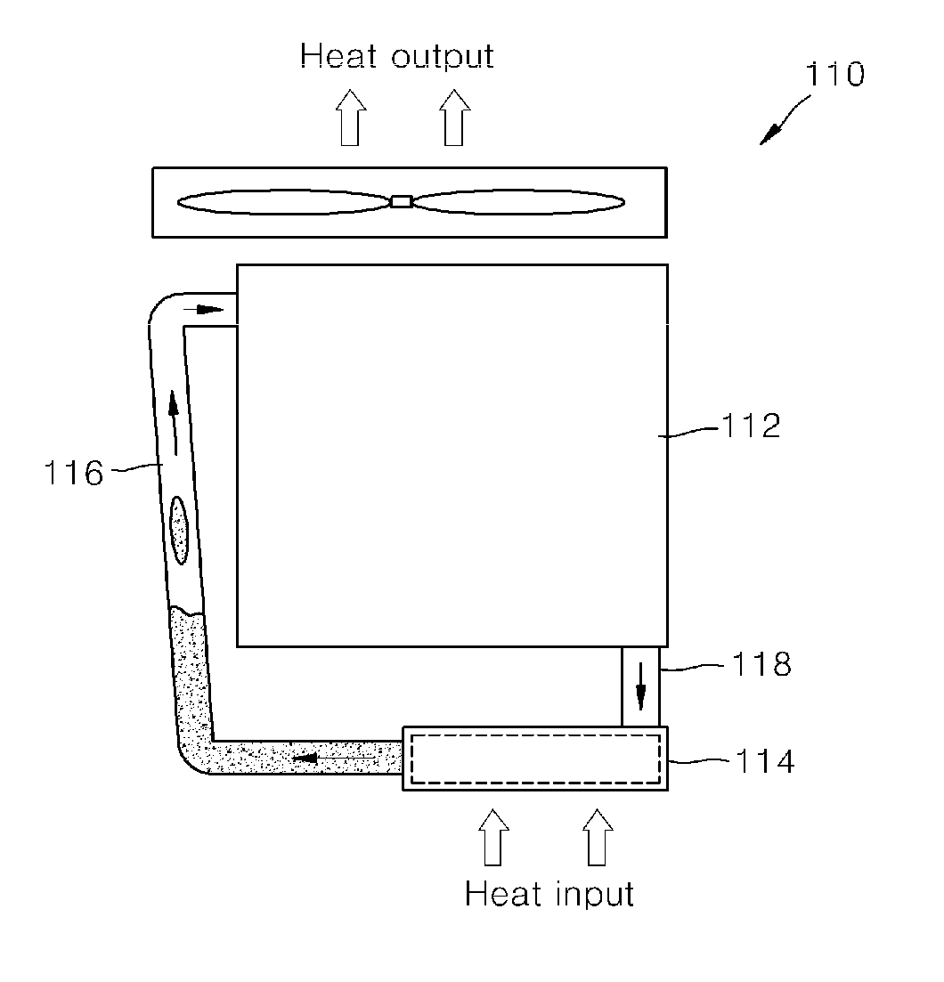
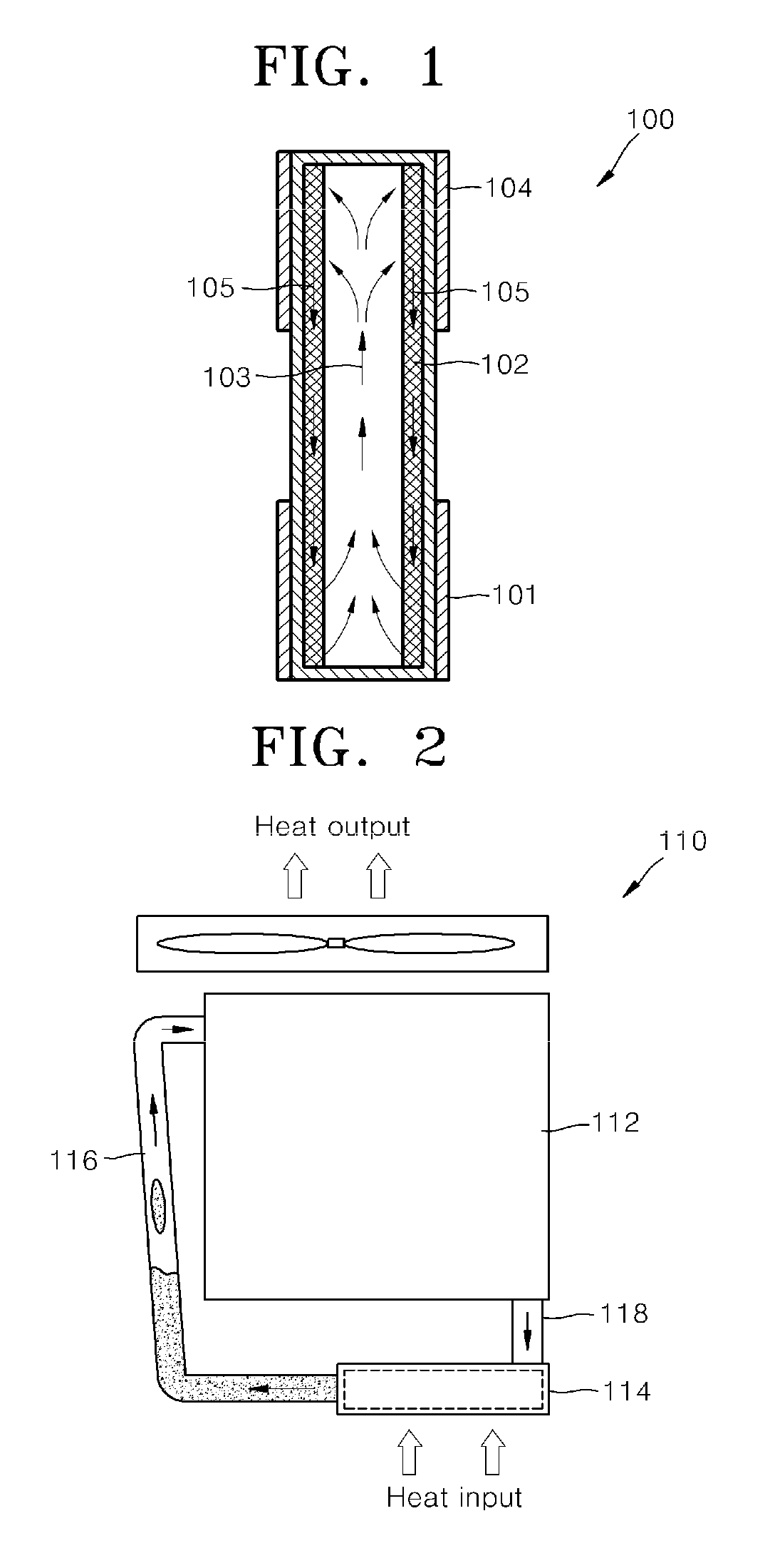
[0033]The present invention is related to an evaporator for a loop heat pipe system including a condenser, a vapor transportation line, and a liquid transportation line. FIG. 6 illustrates the structure of a loop heat pipe system according to an embodiment of the present invention. Referring to FIG. 6, the loop heat pipe system includes an evaporator 1, a condenser 210, a vapor transport line 220, and a liquid transport line 230.

[0034]The condenser 210 changes the phase of a working fluid in a va...


PUM


Abstract

Provided is an evaporator for a loop heat pipe system including a condenser, a vapor transport line, and a liquid transport line, and more particularly, to an evaporator having an increased contact area between a sintered wick and a heating plate.

Description

CROSS-REFERENCE TO RELATED APPLICATIONS[0001]The present application is a continuation of pending International patent application PCT / KR2008 / 004493 filed on Aug. 1, 2008 which designates the United States and claims priority from Korean patent application 10-2008-0057458 filed on Jun. 18, 2008, the content of which is incorporated herein by reference.FIELD OF THE INVENTION[0002]The present invention relates to an evaporator for a loop heat pipe system including a condenser, a vapor transport line, and a liquid transport line, and more particularly, to an evaporator having an increased contact area between a sintered wick and a heating plate.BACKGROUND OF THE INVENTION[0003]Electronic parts such as CPUs or semiconductor chips used for various electronic devices such as computers generate a large amount of heat during operation. Such electronic devices are usually designed to operate at room temperature. Accordingly, when heat generated during the operation of an electronic device is...

Claims


Application Information

Patent Timeline
Patent Type & Authority Applications(United States)
IPC IPC(8): F28D15/04
CPCF28D15/046F28D15/043
Inventor KIM, CHUL JUSEO, MIN-WHANSUNG, BYUNG-HOYOO, JUNG-HYUNCHOI, JEE-HOONKI, JAE-HYUNG
Owner ZALMAN TECH CO LTD
Why Eureka
Try Eureka