Flow diverters to enhance heat sink performance

a heat sink and flow diverter technology, applied in the field of heat sinks, can solve the problems of liquid cooling adding significant costs and reliability concerns to system design, components dispersing, and air-cooled heat sinks becoming inadequate to sufficiently cool these devices

Inactive Publication Date: 2009-12-31
ALCATEL-LUCENT USA INC
View PDF9 Cites 49 Cited by
  • Summary
  • Abstract
  • Description
  • Claims
  • Application Information

AI Technical Summary

Problems solved by technology

Some electronic components dissipate enough power that air-cooled heat sinks are becoming inadequate to sufficiently cool these devices.
Liquid cooling adds significant costs and reliability concerns to system designs, and is thus undesirable in many cases.

Method used


Image

  • Flow diverters to enhance heat sink performance
  • Flow diverters to enhance heat sink performance
  • Flow diverters to enhance heat sink performance

Examples


Embodiment Construction

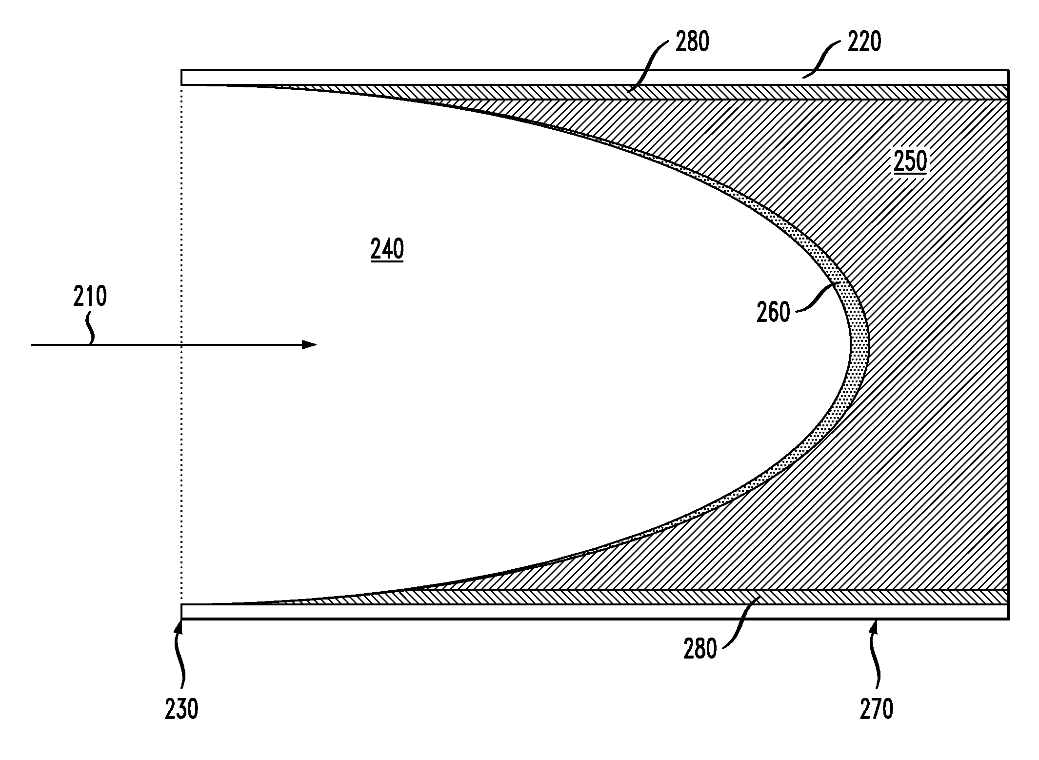
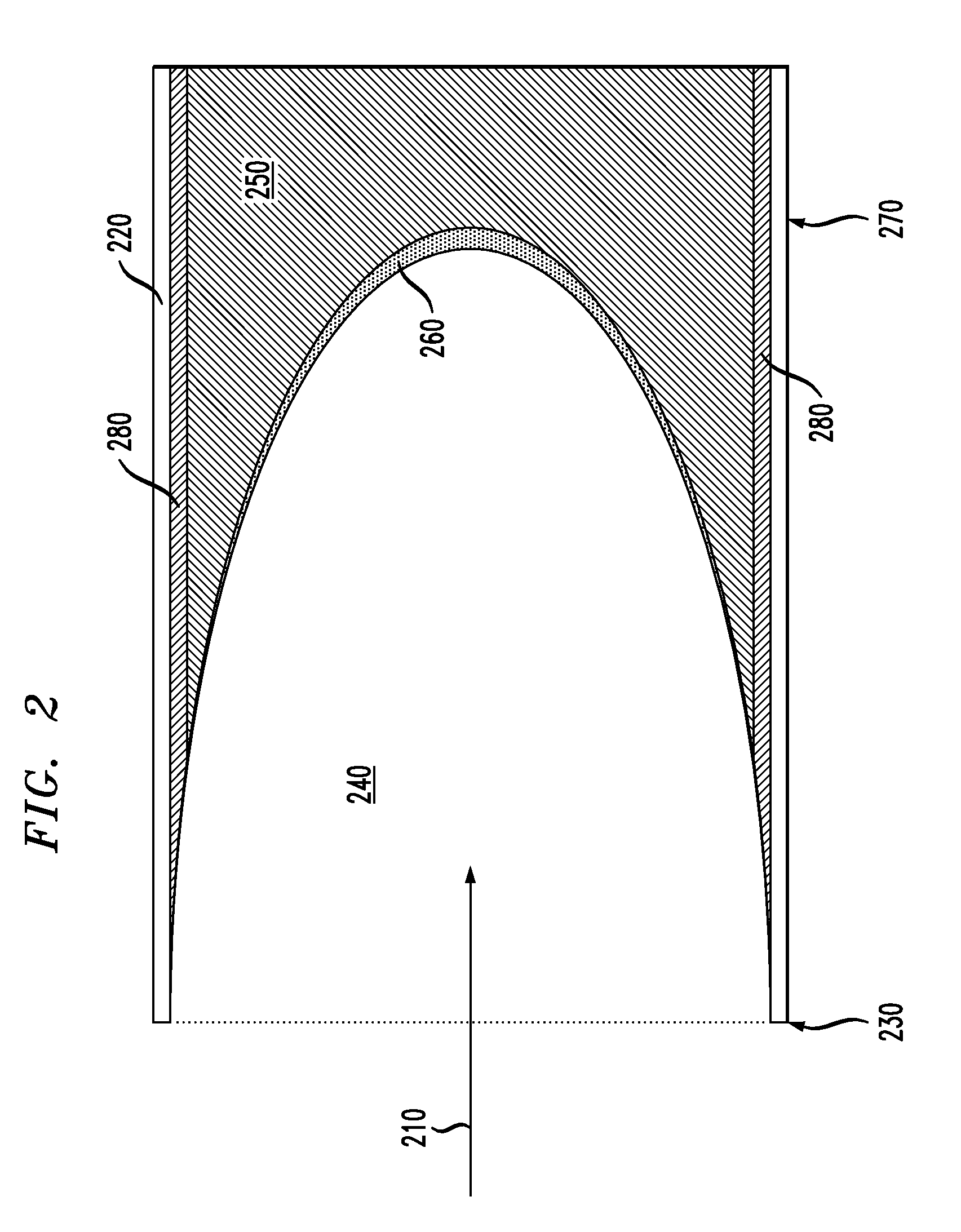
[0011]Embodiments described herein reflect the recognition that structural features may be used in heat sinks that decrease thermal resistance between the heat sink and a fluid e.g., air. In some embodiments, these structural features may be used to produce unsteady flow of air, e.g., in selected portions of the heat sink to disturb laminar flow near surfaces of the heat sink. In other embodiments, features are formed that direct cooler, faster moving air from one region of a heat sink to a region having hotter, slower flow to increase the rate of heat transfer from the hotter regions. In some embodiments, three dimensional (3-D) rendering and investment casting may be employed to form such structural features in a cost-effective manner.

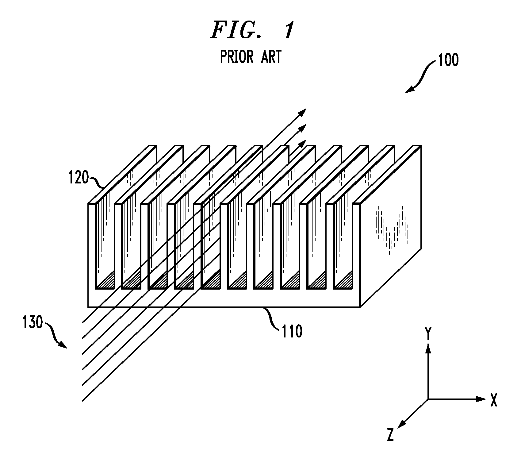
[0012]FIG. 1 illustrates a prior art heat sink 100. Features of the heat sink 100 include a base 110 and fins 120. The fins 120 of such heat sinks are typically structurally uniform, e.g., there are no projections or depressions in the surface of the...


PUM

PropertyMeasurementUnit
Reynolds numberaaaaaaaaaa

Abstract

A heat sink includes a base and fins attached to the base. A flow diverter is in contact with the base or at least one of the fins and is configured to disturb a laminar flow region of a fluid flowing adjacent to at least one of the fins or the base.

Description

CROSS-REFERENCE TO RELATED APPLICATIONS[0001]The present application is related to U.S. patent application Ser. No. ______ to Hernon, et al., entitled “Active Heat Sink Designs”, and which is commonly assigned with the present application, and U.S. patent application Ser. No. ______ to Hernon, et al., entitled “Monolithic Structurally Complex Heat Sink Designs,” both of which are hereby incorporated by reference as if reproduced herein in their entirety.TECHNICAL FIELD OF THE INVENTION[0002]The present invention is directed, in general, to heat sinks.BACKGROUND OF THE INVENTION[0003]Heat sinks are commonly used to increase the convective surface area of an electronic device to decrease the thermal resistance between the device and cooling medium, e.g., air. Such heat sinks generally employ fins or pins to exchange heat with a fluid (air or liquid) flowing thereover. Some electronic components dissipate enough power that air-cooled heat sinks are becoming inadequate to sufficiently c...

Claims


Application Information

Patent Timeline
Patent Type & Authority Applications(United States)
IPC IPC(8): F28F7/00
CPCF28F13/02H01L23/467B23P15/26Y10T29/4935H01L2924/0002F28F3/02H01L2924/00F28F13/06F28F2215/10
Inventor HERNON, DOMHNAILLHODES, MARCLYONS, ALANO'LOUGHLIN, ALANKRISHNAN, SHANKAR
Owner ALCATEL-LUCENT USA INC
Why Eureka
Try Eureka