Lounge chair cushion cover and method
a lounge chair and cushion cover technology, applied in the field of lounge chairs, can solve the problems of not meeting the needs of towels alone, not creating the surface comfort of high-end hotels and resorts, and more expensive chaise lounges, and achieve the effect of reducing slack and folding
- Summary
- Abstract
- Description
- Claims
- Application Information
AI Technical Summary
Benefits of technology
Problems solved by technology
Method used
Image
Examples
first embodiment
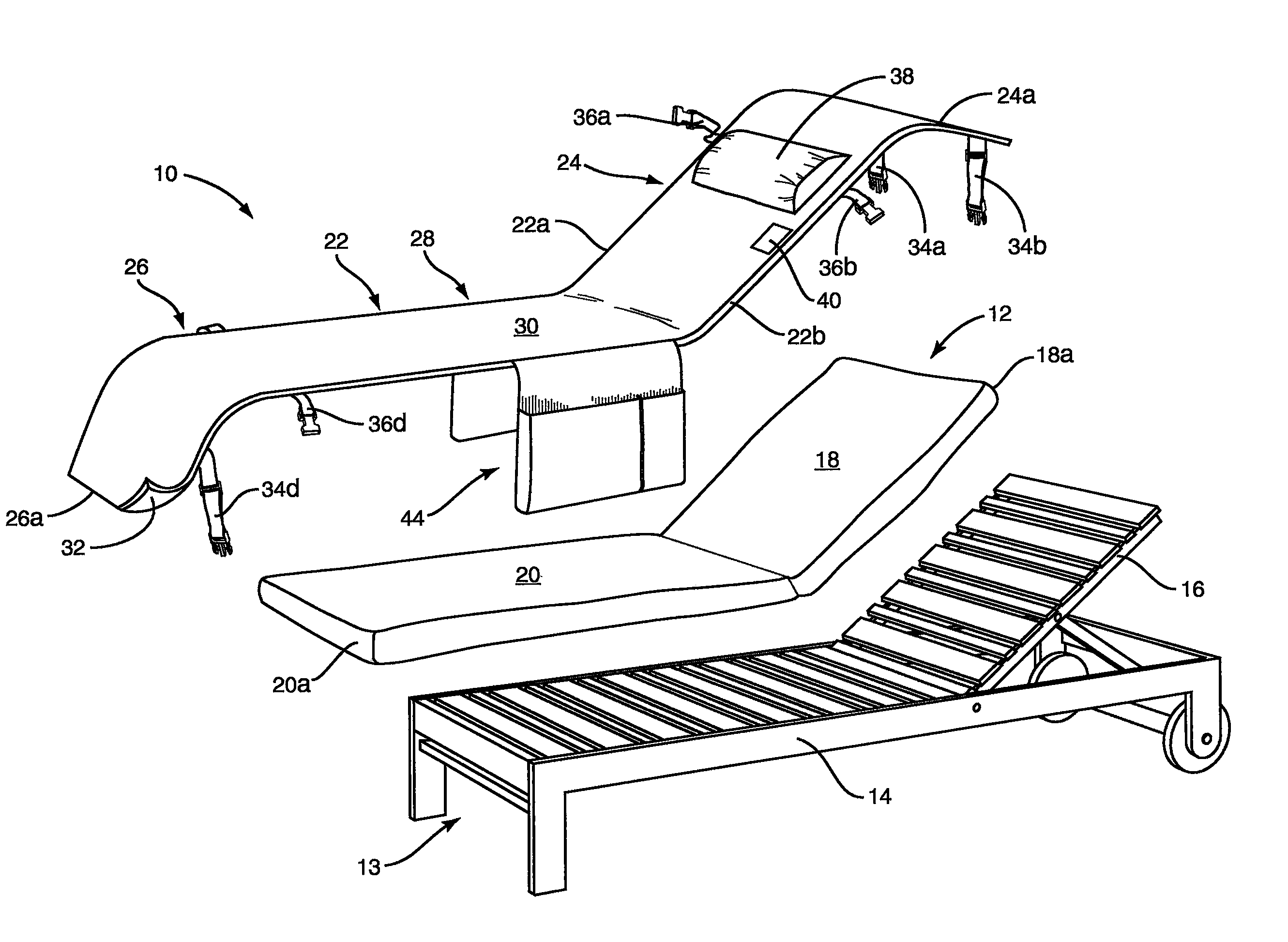
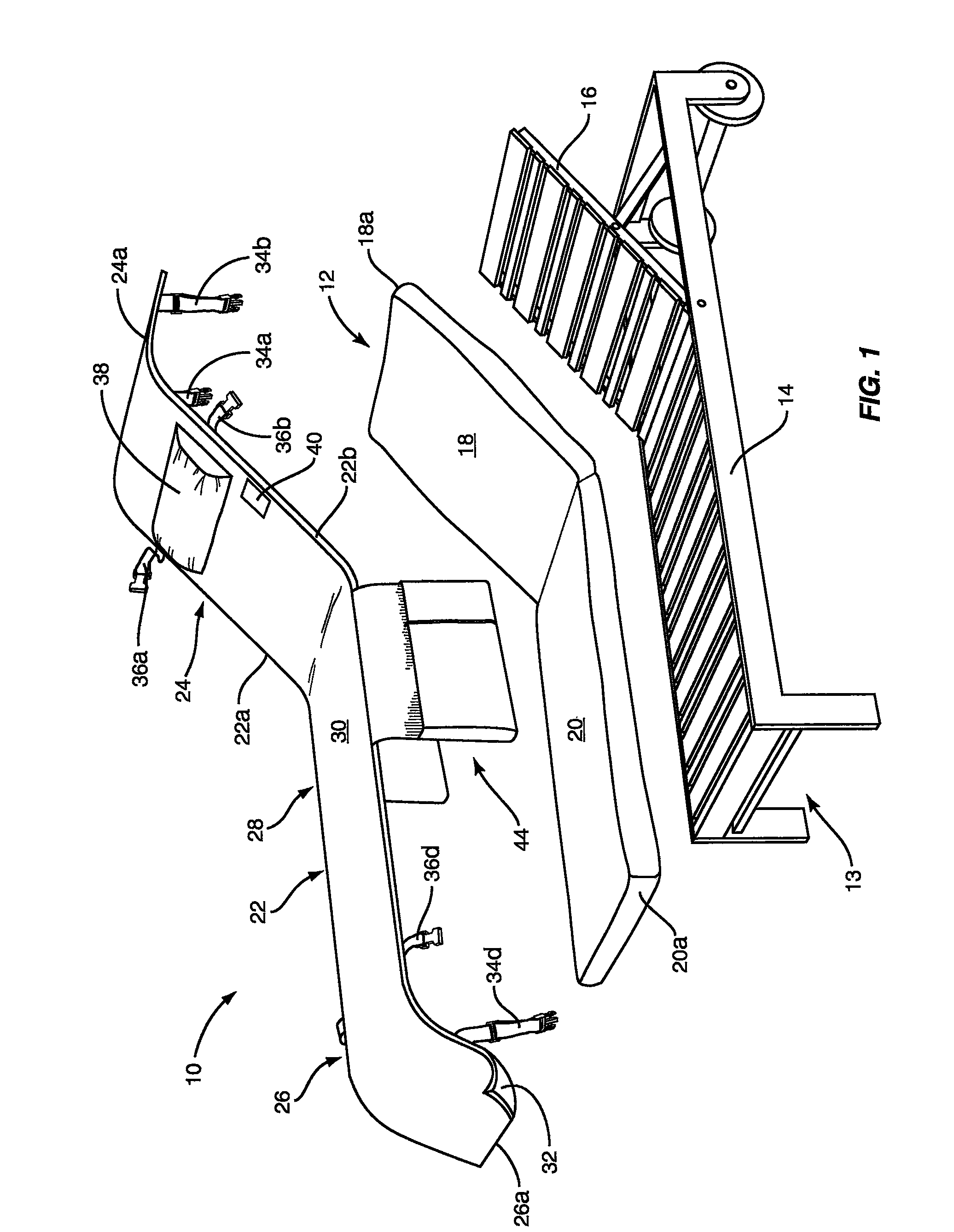
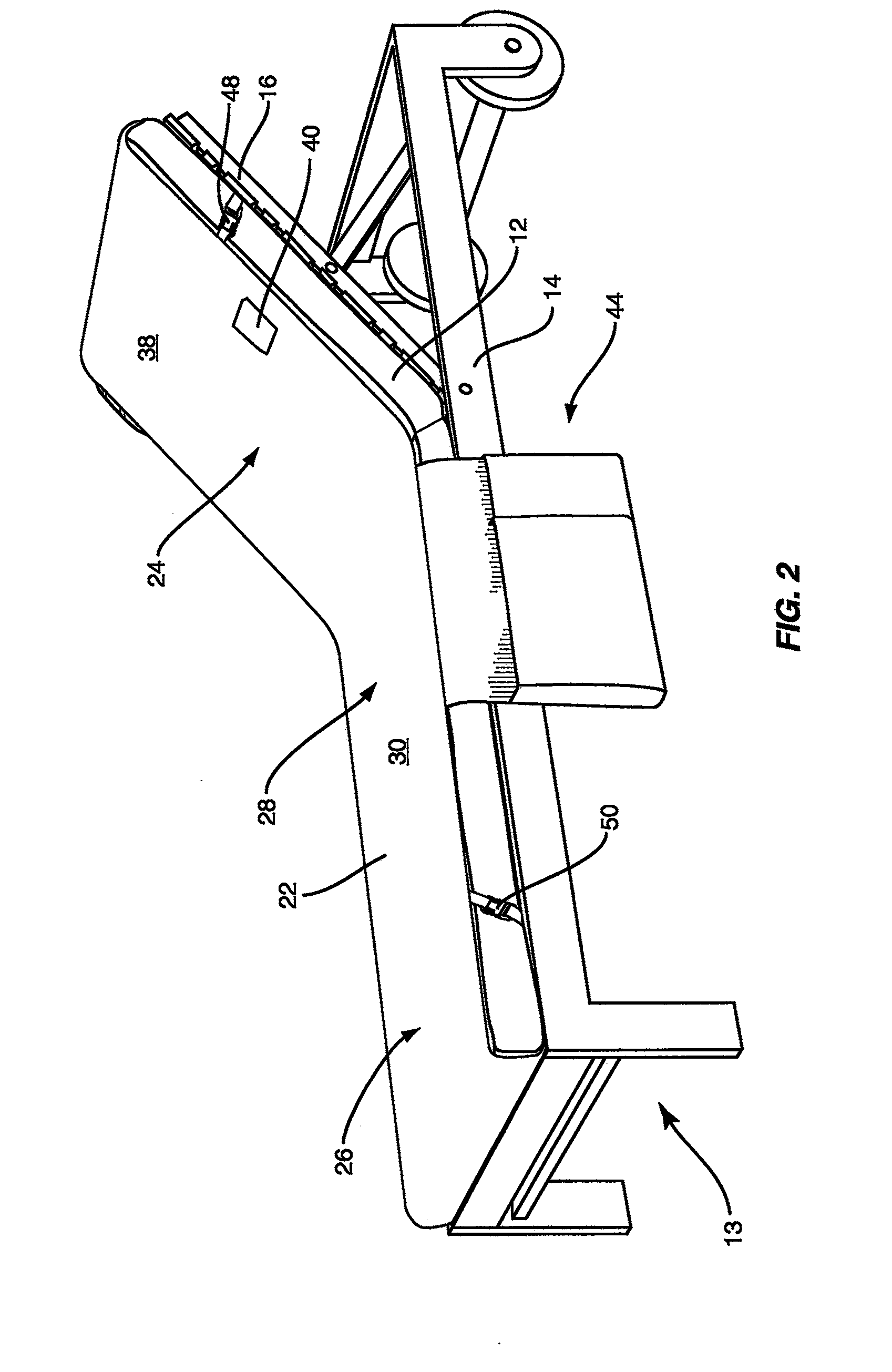
[0025]FIGS. 1-3, illustrates a cover 10 constructed in accordance with a FIG. 1 shows the positional relationship between the cover 10, the chaise lounge pad 12, and a conventional chaise lounge frame 13 having a seat / foot portion 14 and an adjustable back / head portion 16. Pad 12 removably rests on and substantially covers the seat / foot and back / head portions 14, 16 of the frame 13. Pad 12 has an upper portion 18 superposed upon the back / head portion 16 when in use, the upper portion 18 terminating in an upper pad end 18a, and a lower portion 20 superposed upon the seat / foot portion 14 when in use, the lower portion 20 terminating in a lower pad end 20a
[0026]Cover 10 includes a sheet 22 preferably constructed of an elongated, generally rectangular terry cloth fabric member. However, sheet 22 may also be constructed of any other material providing comfort and convenience to the user, such as cotton, MicroCotton®, zero-twisted cotton, or other similar fabrics. Sheet 22 is of suffici...
second embodiment
[0034]FIGS. 4C and 6 show a cover 210 constructed in accordance with a second embodiment, similar to that shown in FIGS. 1-3, except showing a different type of releasable securing device provided on the ends of the straps, and a plurality of openings formed along each side of the sheet at the head portion and front portion. Straps in the form of cords 74, 76, 78, and 80 extend laterally from, and are attached at proximal ends thereof, to each side 222a, 222b of the sheet 222 proximate opposing ends 222c, 222d of the sheet. Respectively attached to the distal, free ends of the cords 74, 76, 78, 80 are button or T-bar members 82, 84, 86, and 88, which are each preferably shaped as cylinders although any shape that can hold the cover in place would also suffice. A plurality of openings 90a-d, 92a-d, 94a-d, and 96a-d are formed into the sheet 222 and are longitudinally positioned along each side of the head portion 224 and the foot portion 226 for receiving the cords 74, 76, 78, 80, pa...
third embodiment
[0035]FIG. 6 shows a plan view of the The ends of the illustrated cords 76 and 80, bearing respective T-bars 84 and 88, are threaded through corresponding openings and then secured to adjustably secure the cover 210 to the pad 12. The user may select which openings receive the cords 76 and 80, depending upon the thickness of the pad 12 (see FIG. 4C). For example, button or T-bar member 88 is shown as having been pressed through opening 96b. T-bar member 88 may be rotated after such passing if doing so provides a further securing against the button being unintentionally pulled back through opening 96b when in use. For instance, if member 88 is cylindrical in shape and opening 96b is a slit, rotating the member 88 so that the axis of the cylinder shape is substantially perpendicular to the lengthwise axis of the slit 96b would serve to resist disengagement of the member 88 from that opening. To facilitate a snug attachment of cover 210 on pad 12, the cords themselves may either be ad...
PUM
 Abstract
Description
Claims
Application Information
 - R&D
- Intellectual Property
- Life Sciences
- Materials
- Tech Scout
- Unparalleled Data Quality
- Higher Quality Content
- 60% Fewer Hallucinations
Browse by: Latest US Patents, China's latest patents, Technical Efficacy Thesaurus, Application Domain, Technology Topic, Popular Technical Reports.
© 2025 PatSnap. All rights reserved.Legal|Privacy policy|Modern Slavery Act Transparency Statement|Sitemap|About US| Contact US: help@patsnap.com


