Method to cut apertures in a material

a material and aperture technology, applied in the field of material aperture forming, can solve the problems of cumbersome masks, uncomfortable masks for users, and the comfort aspect of mask treatment remains a difficult aspect of mask treatment, and achieve the effects of quiet operation, economical mask production, and quiet operation

Inactive Publication Date: 2009-10-01
CIRCADIANCE
View PDF17 Cites 5 Cited by
  • Summary
  • Abstract
  • Description
  • Claims
  • Application Information

AI Technical Summary

Benefits of technology

[0009]The dispersion of small apertures also buffers the air flow exiting the mask thus avoiding a bothersome air stream that may blow against the skin of the mask user or the bed partner and disturb sleep. The perforated array technique also allows for quieter operation of the mask. The quiet operation is especially important because such masks are most often used at night.
[0010]It should also be noted that the array of apertures can be arranged in a “dot matrix” manner to graphically create an image. This technique is useful in product branding, identification or production run identification. The application of laser technique allows for an apparatus which is very lightweight, flexible and compliant to the face of the user. The application of the laser technique allows for the economical production of the mask and provides for very repeatable production output.
[0011]The highly accurate nature of laser cutting allows for the creation of an array of apertures that serve as an exhaust valves for air flow without adding undue cost, complexity or weight to the product.
[0012]Laminated fabric cloth layer and a plastic layer is used to create a material which is soft and non-abrasive to human skin, but which is impermeable to air flow. Rectangular pieces of material are placed onto the cutting bed of a 30 watt CO2 laser. A program to optimize material consumption and minimize folds and seams is loaded into the computer which controls the actions of the laser. All cutting and marking is done in the X-Y plane. The Z position is carefully set to the prescribed focal length for this particular laser. The profile cutting of the silhouette is done in vector cutting mode, but the laser also executes in raster mode at varying power settings to mark the material with critical information such as production lot and to execute the raster pattern that becomes the exhalation apertures. The cut pattern is sewn into a final product as described in patent application filed Feb. 28, 2008 entitled “Apparatus To Provide Continuous Positive Airway Pressure”, no serial number has been assigned. The resulting product exhibits ease of use, comfort and reliable performance.

Problems solved by technology

However, the use a laser to form precise apertures in material to for use as exhaust valves in positive pressure masks and other uses as vents is not described in the prior art.
This has lead to a generation of masks which are cumbersome and uncomfortable for the user.
Despite the many advances made in the science of the treatment of Obstructive Sleep Apnea, mask comfort remains a difficult aspect of the treatment of this condition.

Method used


Image

  • Method to cut apertures in a material
  • Method to cut apertures in a material
  • Method to cut apertures in a material

Examples


Embodiment Construction

, particularly, when such description is taken in conjunction with the attached drawing figures and with the appended claims.

BRIEF DESCRIPTION OF THE DRAWINGS

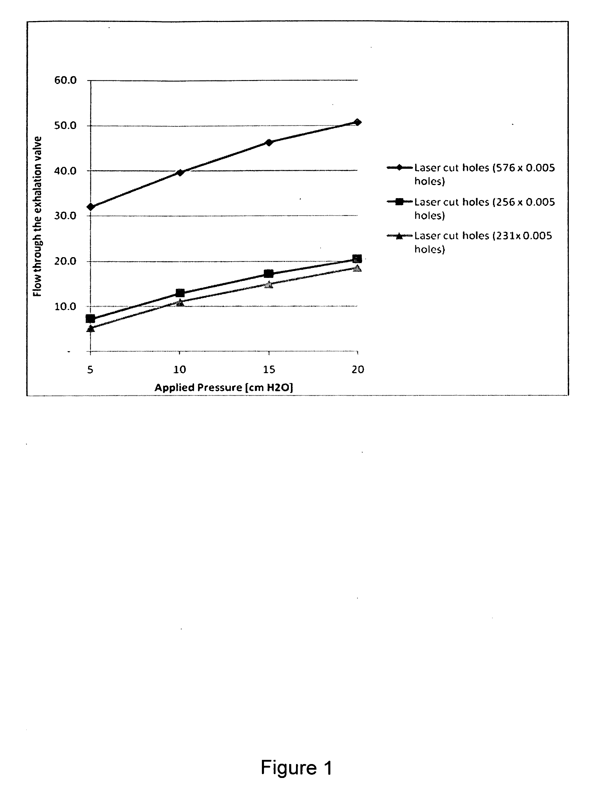
[0022]FIG. 1 is a diagram of flow through the exhalation valve vs. the applied pressure.

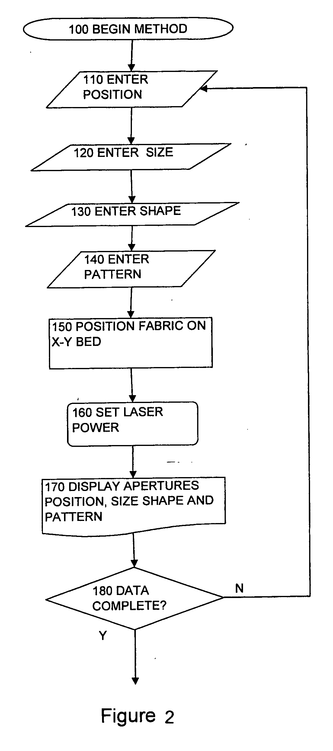
[0023]FIG. 2 is a flow chart of the presently preferred embodiment of the method.

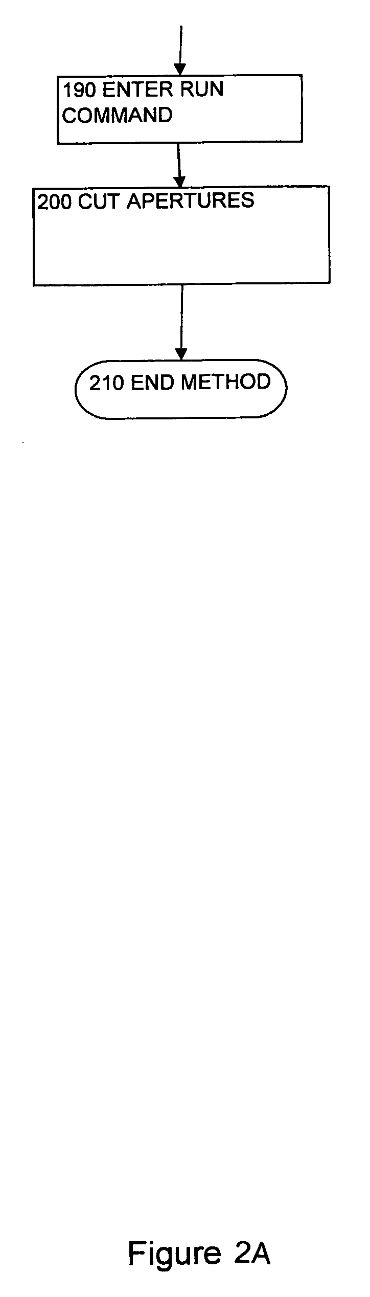
[0024]FIG. 2A is a flow chart that is a continuation of FIG. 2.

BRIEF DESCRIPTION OF A PRESENTLY PREFERRED AND VARIOUS ALTERNATIVE EMBODIMENTS OF THE INVENTION

[0025]Prior to proceeding to the more detailed description of the present invention it should be noted that, for the sake of clarity and understanding, identical components which have identical functions have been identified with identical reference numerals throughout the several views illustrated in the drawing figures.

[0026]Reference is now made, more particularly, to FIG. 2. Using a computer with cutting control software, a laser and x-y bed, the user enters aperture.

[0027]The user enters position info...


PUM

PropertyMeasurementUnit
sizeaaaaaaaaaa
total geometric areaaaaaaaaaaa
geometric areaaaaaaaaaaa

Abstract

A method is described for the cutting of apertures in a material using a computer, laser control software, input device, laser and an x-y plotting bed. The method is to preferably form apertures in fluid impermeable material including composite materials. The apertures are used as exhaust valves in positive pressure masks to deliver breathable gas to patients and in garments.

Description

FIELD OF THE INVENTION[0001]The present invention relates, in general, to a method of forming precise apertures in material and, more particularly, this invention relates to a method of forming apertures in material to control air flow in positive pressure masks.BACKGROUND OF THE INVENTION[0002]Prior to the conception and development of the present invention, as is generally well known in the prior art, to use a laser to cut fabric and film. The use of a bed to hold the work piece is well known. Pulse lasers to cause ablation to materials and to prepare cells in nonwoven fabric are known. However, the use a laser to form precise apertures in material to for use as exhaust valves in positive pressure masks and other uses as vents is not described in the prior art.[0003]In the U.S. non provisional application No. ______ filed Feb. 28, 2008, a face mask is described that is used to treat persons with Obstructive Sleep Apnea. Treatment involves applying a positive pressure to the person...

Claims


Application Information

Patent Timeline
Patent Type & Authority Applications(United States)
IPC IPC(8): B23K26/38
CPCA61M16/06A61M16/208A61M2205/7536B23K26/0807B23K26/0823B23K2203/16B23K26/0869B23K26/383B23K26/4065B23K26/409B23K26/0853B23K26/40B23K26/082B23K26/384B23K2103/16B23K2103/172B23K2103/42B23K2103/50
Inventor GROLL, DAVID G.GROLL, WILLIAM A.MILNTHORP, JOHN
Owner CIRCADIANCE
Why Eureka
Try Eureka