Drive Circuit for Piezoelectric Pump and Cooling System That Uses This Drive Circuit

a technology of drive circuit and piezoelectric pump, which is applied in the direction of piston pumps, instruments, and piezoelectric/electrostrictive device details, can solve the problems of increasing the size of the device, and achieve the effects of reducing pointless power consumption, reliable operation, and quiet operation

Inactive Publication Date: 2007-10-18
NEC CORP
View PDF3 Cites 26 Cited by
  • Summary
  • Abstract
  • Description
  • Claims
  • Application Information

AI Technical Summary

Benefits of technology

[0039] As the first effect of the present invention, the drive waveform of the piezoelectric pump is a sine wave, whereby the piezoelectric pump can realize quiet operation as a cooling device without generating undesirable vibrational noise from the piezoelectric pump.
[0040] As the second effect, even when bubbles are present in the pump chamber of the pump, these bubbles are expelled at the time of activation, whereby the inability to begin circulation of liquid due to inadequate pressure can be solved and reliable operation realized.
[0041] As the third effect, when the heat-generating body is not discharging heat, the drive voltage of the piezoelectric element of the piezoelectric pump can be decreased to thus reduce pointless power consumption by the drive circuit and suppress the generation of heat.

Problems solved by technology

Normally, a low-frequency transformer is used as the above-described inverter circuit, but the use of a low-frequency transformer increases the size of the device and necessitates large packaging space and thus raises problems when used in mobile equipment that requires a compact and thin form.

Method used


Image

  • Drive Circuit for Piezoelectric Pump and Cooling System That Uses This Drive Circuit
  • Drive Circuit for Piezoelectric Pump and Cooling System That Uses This Drive Circuit
  • Drive Circuit for Piezoelectric Pump and Cooling System That Uses This Drive Circuit

Examples


first embodiment

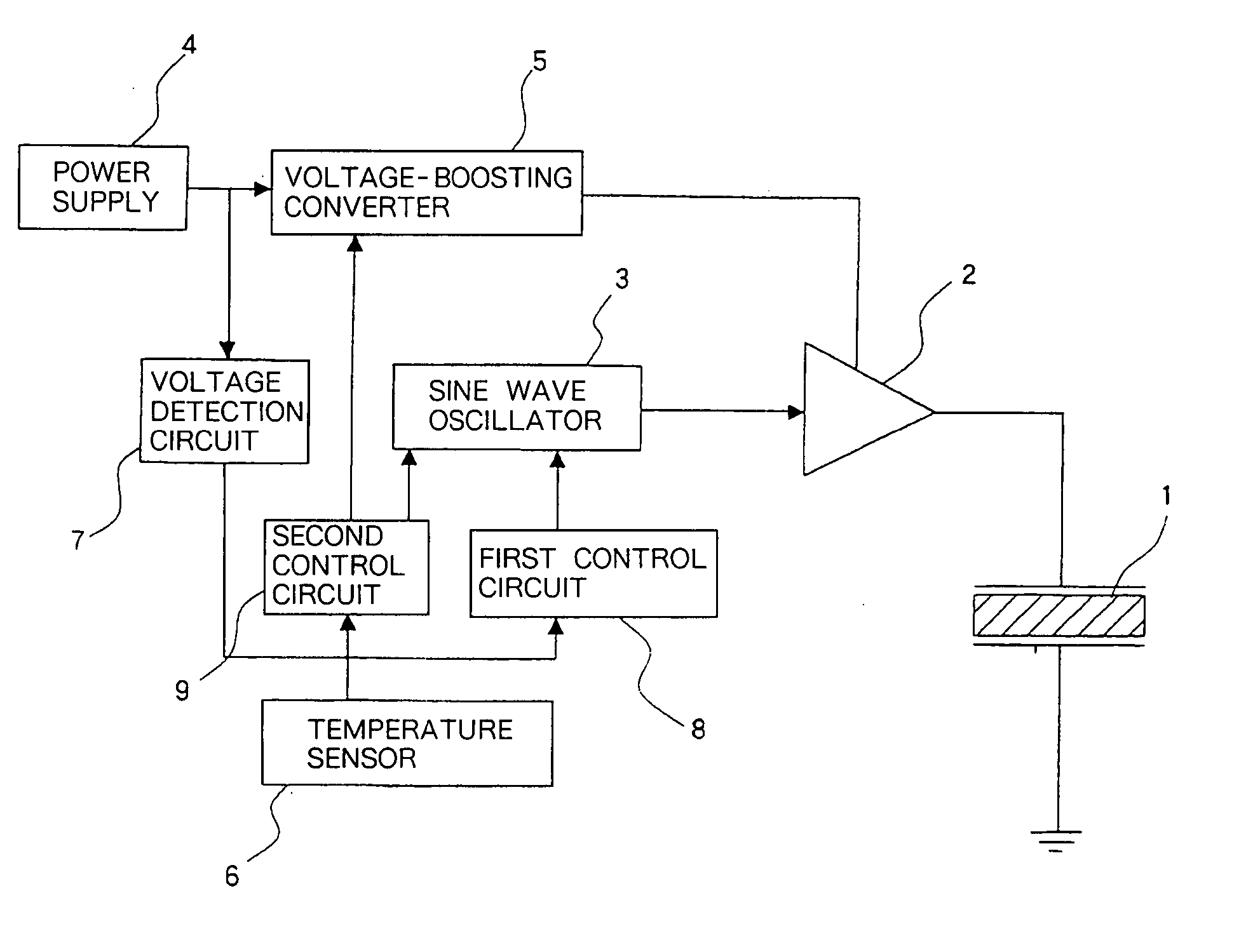
[0086]FIG. 4 is a block diagram giving a schematic view of the configuration of the piezoelectric pump drive circuit according to the present invention, and FIG. 5 is a block diagram showing greater detail.

[0087] As shown in FIG. 4, the present embodiment is made up from: piezoelectric element 1, amplifier 2, sine wave oscillator 3, power supply 4, voltage-boosting converter 5, temperature sensor 6, voltage detection circuit 7, first control circuit 8, and second control circuit 9.

[0088] Piezoelectric element 1 that drives the piezoelectric pump (not shown) is driven by amplifier 2 that takes as input a sine wave signal generated in sine wave oscillator 3. In addition, amplifier 2 is driven at a voltage that is obtained by conversion from low-voltage power supply 4 to high voltage by means of voltage-boosting converter 5. As a result, piezoelectric element 1 is driven by a high-voltage sine wave voltage.

[0089] The frequency or amplitude of sine wave oscillator 3 is controlled in a...

second embodiment

[0099] Explanation next regards the present invention.

[0100] The basic configuration of this embodiment is similar to that of the first embodiment, but a D-class amplifier, which is typically employed in audio applications, is used for the amplifier. FIG. 8 shows the configuration.

[0101] In FIG. 8: 20 is a D-class amplifier; 21 is a PWM modulator; 22 is an output switch unit; 22a, 22b, 22c, and 22d are a first switch, a second switch, a third switch, and a fourth switch, respectively; 23 is a low-pass filter; 23a is a first inductor; 23b is a first capacitor; 23c is a second inductor; 23c is a second capacitor; 24a is a first inverter circuit; and 24b is a second inverter circuit. In addition, constituent elements that are identical to elements of the first embodiment have been given the same reference numbers, and redundant explanation is therefore here omitted.

[0102] In the present embodiment, D-class amplifier 20 is used as amplifier 2. The signal that is supplied as output fro...


PUM


Abstract

A drive circuit of a piezoelectric pump that is both light and compact, that can drive a piezoelectric pump with a low level of undesired noise, and that can further realize with low power consumption a coolant device capable of reliable operation at the time of activation. A piezoelectric element of the piezoelectric pump is driven by the output signal of an amplifier that takes as input a signal that is generated by a sine wave oscillator of the same frequency that drives the piezoelectric element. The amplifier is driven by a high voltage obtained by conversion from a low-voltage power supply by a voltage-boosting converter, whereby the piezoelectric element is driven by a low-frequency sine wave of high voltage. The frequency of the sine wave oscillation is further adjusted by a signal from a first control circuit at the time of activation. In addition, the amplitude of the sine wave oscillation is adjusted by the output signal of a second control circuit that takes as input a signal from temperature sensor for sensing the temperature of the heat-generating body.

Description

TECHNICAL FIELD [0001] The present invention relates to a drive circuit for a piezoelectric pump used in a cooling device for cooling a heat-generating body of an electronic component, and to a cooling system that uses this drive circuit. BACKGROUND ART [0002] Processors for high-speed processing are used in, for example, notebook computers, and cooling devices are required for reducing the rise in temperature caused by the heat generated by this equipment. One such cooling method of this type in the prior art is the water-cooled method that employs a piezoelectric pump as described in JP-A-2001-355574. [0003] When using a piezoelectric pump, an alternating current at a voltage of approximately 100V is required as the drive voltage to produce a large displacement when deforming the piezoelectric material that is used in the piezoelectric pump. In addition, the drive frequency is a low frequency of several tens to several hundred Hz due to the response of valves that operate in accor...

Claims


Application Information

Patent Timeline
Patent Type & Authority Applications(United States)
IPC IPC(8): H05K7/20H02N2/00F04B9/00F04B43/04F04B45/047G06F1/20H01L23/473H01L41/04
CPCF04B17/003F04B43/046F04B45/047G06F1/206H01L23/473H01L2924/0002H01L41/042Y02B60/1275H01L2924/00Y02D10/00H10N30/802
Inventor YAMAMOTO, MITSURUHAMAMURA, SUNAOSASAKI, YASUHIROKITAJO, SAKAE
Owner NEC CORP
Why Eureka
Try Eureka