Magnetic door lock assembly

a magnetic door lock and assembly technology, applied in the direction of wing fasteners, construction fastening devices, fastening means, etc., can solve the problems of affecting the operation of the door lock. , to achieve the effect of quiet operation

Inactive Publication Date: 2014-10-30
SECURITECH GROUP
View PDF24 Cites 26 Cited by
  • Summary
  • Abstract
  • Description
  • Claims
  • Application Information

AI Technical Summary

Benefits of technology

[0008]A first object of the present invention is to provide a door latch structure which will allow a latch to automatically engage and lock with a strike plate with a relatively quiet operation.
[0011]A still additional object is to provide a door latch structure as described above which includes a sound damping element situated either in the strike plate subassembly or in the latch assembly in the door, which either slows the movement of the bolt so that it does not impact against a stop element, or by other means deadens the sound of the bolt reaching its stop position.

Problems solved by technology

Regardless of the exact mechanism in the latch assembly that stops the outward motion of the moving bolt, this stopping invariably causes a significant amount of sound in all manner of locks from doors in rooms, automobile doors and frames, luggage locks, etc.
In many cases the sound is annoying or distracting and sometimes detrimental as described below.
In patient rooms in hospitals this clicking or clacking door-closing noise is a particular and potentially serious problem.
Furthermore, door latch clacking in one room would create disturbing noise to patients in adjacent rooms.

Method used


Image

  • Magnetic door lock assembly
  • Magnetic door lock assembly
  • Magnetic door lock assembly

Examples


Embodiment Construction

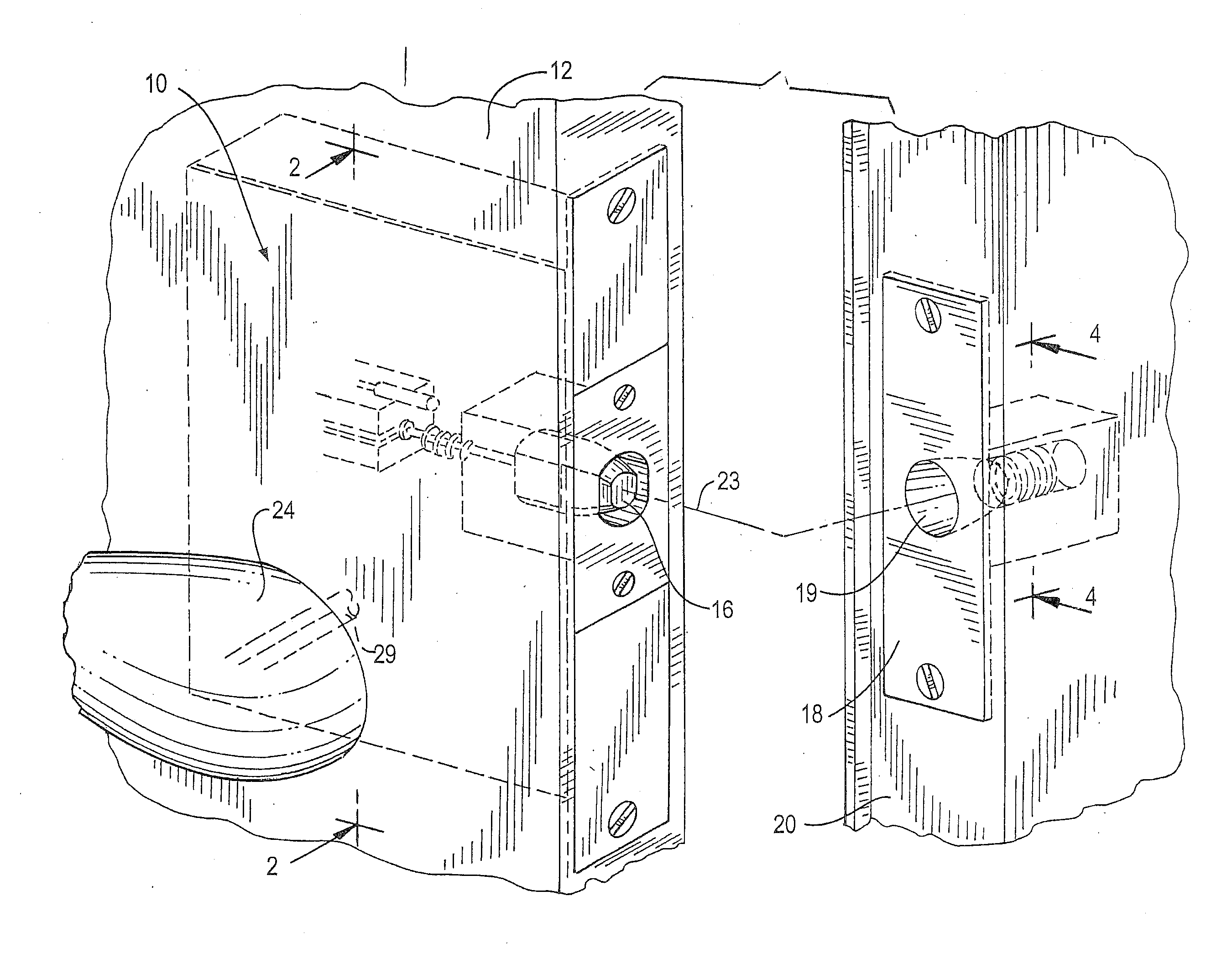
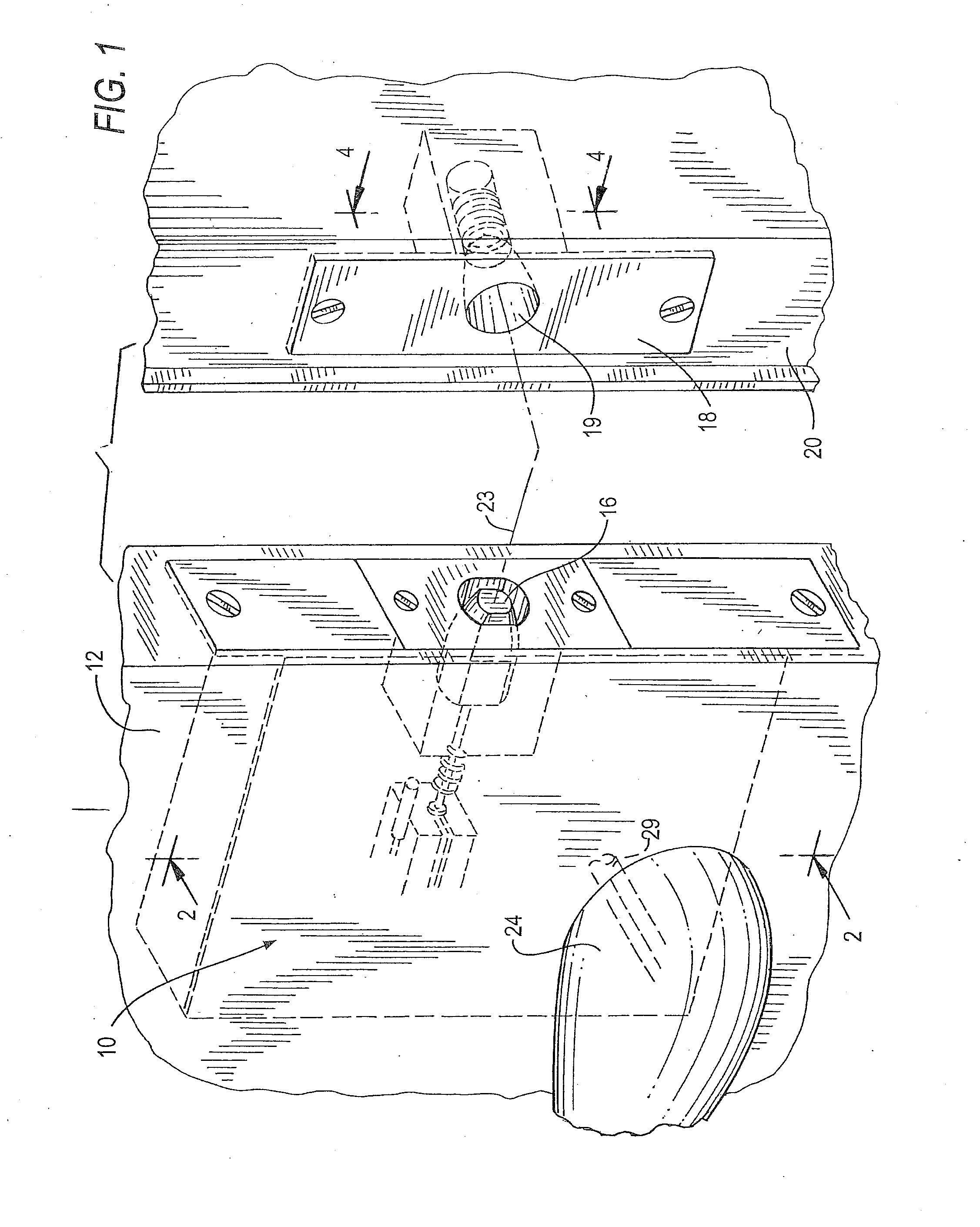
[0033]FIG. 1 illustrates the environment of the present invention which is a door latch assembly 10 situated in a door 12 that is pivotally mounted in a door frame where the door latch assembly's sliding bolt 16 can engage a strike plate 18 situated in door frame 20. Door 12 is shown in a partially open state with its bolt 16 situated to move along dashed line 23 into aperture 19 of strike plate 18 when door 12 completes pivoting to its closed position. Also shown in FIG. 1 is door lever 24 mounted pivotally on door 12 to cooperate with the latch assembly 10 for a person to manually pivot lever 24 to retract bolt 16 from its extended position in a strike plate when the door is closed.

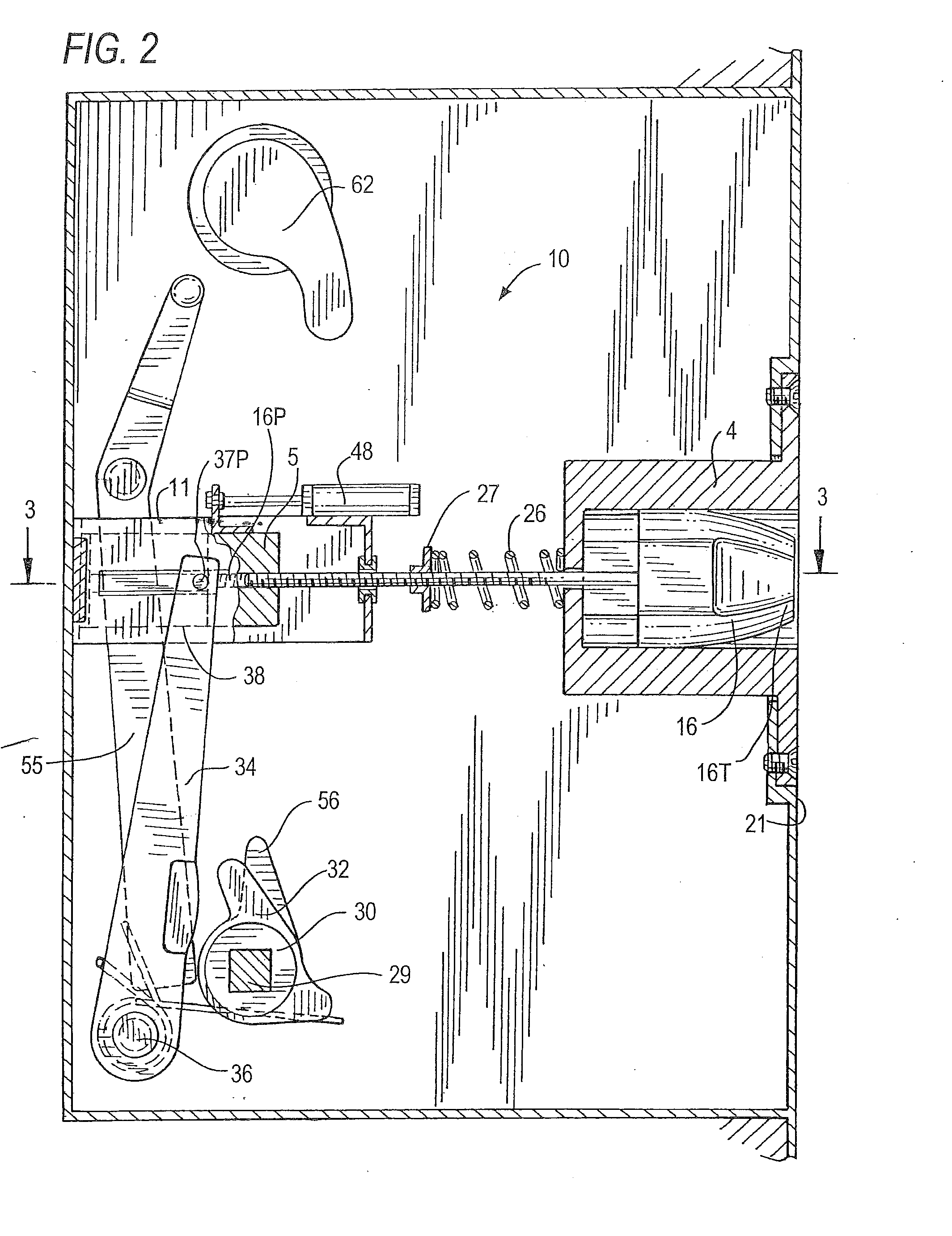
[0034]FIG. 2 illustrates the new latch assembly 10, shown for illustrative purpose, with its front plate removed. As seen, bolt 16 is situated in a retracted position so that its distal end or bolt head 16T does not extend outward of the edge surface 21 of latch housing 12. Bolt 16 can move axially outw...


PUM


Abstract

A latch lock system for a door that is mountable in a doorframe, the latch lock system including a main housing including a spindle and lever, a bolt having a nose part that is attractable to a magnet, the bolt being slidable in the main housing between extended and retracted positions, a spring biasing the bolt to its retracted position, a secondary housing including a strike plate in the doorframe, a magnet mounted in the secondary housing, the magnet having a magnetic force greater than the spring force which will pull the bolt to its extended position when the door is in its closed position and the bolt is aligned with the magnet.

Description

RELATED CASE[0001]This application claims priority under 35 USC Sections 119 and / or 120 of Provisional Patent Application Ser. No. 61 / 791, 998 filed Mar. 15, 2013, owned by the present applicant, the contents of which are incorporated herein by reference,FIELD OF THE INVENTION[0002]This invention is in the field of door lock assemblies and particularly the interaction of a moving bolt of the lock assembly and a cooperating strike plate in a doorframe.BACKGROUND AND PRIOR ART[0003]Door latch assemblies are well known in the prior art including both spring-biased bolts and deadbolts which engage a strike plate in a door frame. A characteristic of spring-biased moving bolts is that the bolt is always resiliently biased to its extended or open position whether the door is open or closed, with the distal part of the bolt inserted into the aperture of a strike plate. When a door closes and the bolt head initially engages the exposed edge of a strike plate, the bolt will momentarily be pus...

Claims


Application Information

Patent Timeline
Patent Type & Authority Applications(United States)
IPC IPC(8): E05C1/08
CPCE05C1/085E05B15/101E05C19/163Y10T292/0999
Inventor BERGER, MARK J.REGEN, JEFFREYZOLTAN, PETER
Owner SECURITECH GROUP
Why Eureka
Try Eureka