Supercharge Your Innovation With Domain-Expert AI Agents!

Sacroiliac joint fusion alignment guide

a technology of alignment guide and sacroiliac joint, which is applied in the field of sacroiliac joint fusion alignment guide, can solve the problems of difficult achieving and maintaining a precise trajectory, damage to the vessels that lie just beyond, and screw penetration into sacral wall or sacral foramina and damage to the nerves of the cauda aquina, etc., to achieve accurate screw placement

Active Publication Date: 2010-01-14
DEPUY SYNTHES PROD INC
View PDF18 Cites 38 Cited by
  • Summary
  • Abstract
  • Description
  • Claims
  • Application Information

AI Technical Summary

Benefits of technology

The present invention provides a sacroiliac joint fusion alignment guide that allows accurate screw placement through the sacroiliac joint during a sacroiliac joint stabilization procedure. The guide is adjustable to fit different patient anatomies. The guide includes a handle and two adjustable guidance arms that define a trajectory for guiding screws and other instruments used in the procedure. The guide is inserted through a posterior incision in the patient and the orientation of the guide is adjusted to determine a suitable trajectory for the screws. The guide helps guide the placement of screws and ensures accurate fusion of the sacroiliac joint.

Problems solved by technology

Iatrogenic (i.e., induced by treatment) procedures, such as iliac bone graft damaging ligaments of the joint and / or previous fusions, can also cause degeneration, requiring sacroliac joint fusion.
If a surgeon places screws on a path too anterior, the screws may penetrate the sacral wall and damage the vessels that lie just beyond.
If a surgeon places screws on a path too posterior, the screws may penetrate the sacral wall or sacral foramina and damage the nerves of the cauda aquina.
Achieving and maintaining a precise trajectory can be difficult in the limited operating space.

Method used


Image

  • Sacroiliac joint fusion alignment guide
  • Sacroiliac joint fusion alignment guide
  • Sacroiliac joint fusion alignment guide

Examples


Embodiment Construction

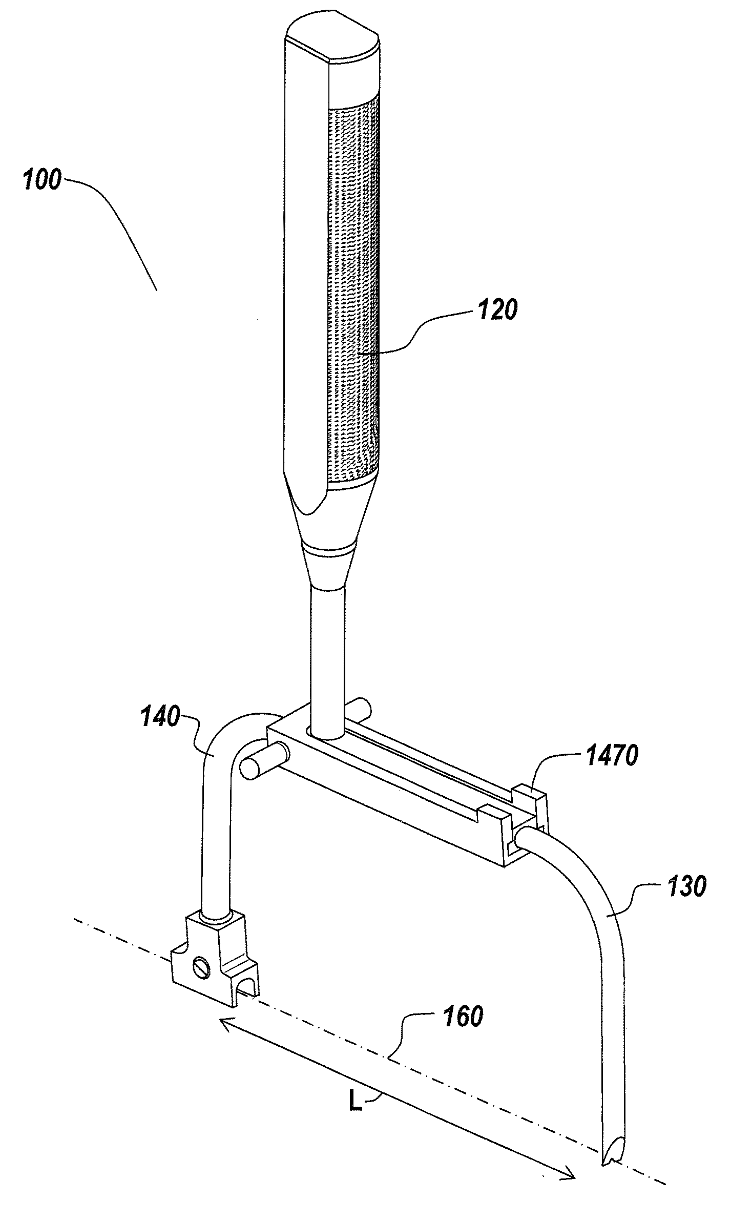
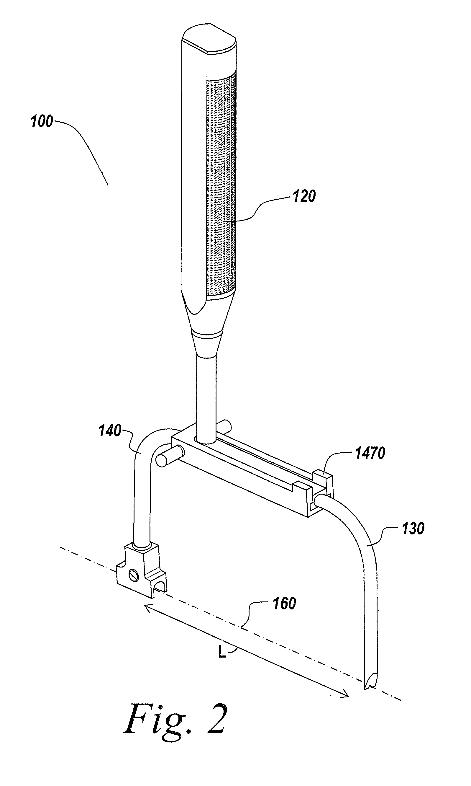
[0023]The present invention provides an improved surgical device and method for performing a sacroiliac joint fusion procedure. The present invention will be described below relative to certain exemplary embodiments in spinal surgery to provide an overall understanding of the principles of the structure, function, manufacture, and use of the instruments disclosed herein. Those skilled in the art will appreciate that the present invention may be implemented in a number of different applications and embodiments and is not specifically limited in its application to the particular embodiments depicted herein. For example, while the illustrative embodiment of the invention relates to a sacroiliac joint fusion alignment guide used in sacroiliac joint fusion surgery, the sacroiliac joint fusion alignment guide may be used in any surgical process where a trajectory is used to guide instruments to a surgical site.

[0024]FIGS. 2-4B illustrate an embodiment of a sacroiliac joint fusion alignmen...


PUM


Abstract

A device and method for defining a trajectory for instruments in a sacroiliac joint fusion procedure employs a handle and two movable guidance arms that are separated by an adjustable distance. The first guidance arm has a substantially straight pronged distal end terminating in a first prong, a second prong and a space between the first prong and second prong defining a first point in a straight trajectory for inserting screws into a sacroiliac joint. The guidance arm forms a receiving bore on a distal end thereof to define a second point in the trajectory. The pronged distal end is inserted through a posterior incision in the patient into a cored-out sacroiliac joint, with the second guidance arm outside the body, and the orientation of the alignment guide is adjusted by pivoting the alignment guide about the pronged distal end to determine a suitable trajectory. Instruments and implements are placed along the trajectory and guided by the alignment guide to drill screw holes and insert screws used in the sacroiliac joint fusion procedure into the screw holes.

Description

RELATED APPLICATION[0001]This application is a divisional application, of U.S. patent application Ser. No. 11 / 406,888, filed Apr. 19, 2006.FIELD OF THE INVENTION[0002]The present invention relates to a device and method for applying screws to fuse a sacroiliac joint in a patient.BACKGROUND OF THE INVENTION[0003]The sacroiliac (SI) joint 10 is located between the sacrum 11 and the hip bones 12, known as the ilium, in the human body, as shown in FIG. 1, and functions to transmit forces from the spine 14, including vertebrae 14a, intervertebral discs 14b and the coccyx 14c, to the lower extremities. The sacroiliac joint 10 is supported by ligaments and muscle. The sacroiliac joint 10 can degenerate over time, requiring a fusion procedure to stabilize the degenerated segment. For example, one condition, degenerative sacroiliitis, results in a narrow joint space with bone spur formation. Iatrogenic (i.e., induced by treatment) procedures, such as iliac bone graft damaging ligaments of th...

Claims


Application Information

Patent Timeline
Patent Type & Authority Applications(United States)
IPC IPC(8): A61B17/58
CPCA61B17/1742A61B17/1739
Inventor ISAZA, JORGE EDUARDOJONES, BRYAN S.HERARD, KATHERINE H.TECHIERA, RICHARD
Owner DEPUY SYNTHES PROD INC
Features
  • R&D
  • Intellectual Property
  • Life Sciences
  • Materials
  • Tech Scout
  • Unparalleled Data Quality
  • Higher Quality Content
  • 60% Fewer Hallucinations
Learn More