Dynamic emergency escape indicator

a technology of emergency escape and indicator, applied in the direction of advertising, signalling system, identification means, etc., can solve the problems of difficulty in escape, even casualties, and people can only escape from the scene of fire in the most primitive way

Inactive Publication Date: 2010-01-21
CHEN JUEI CHAO
View PDF7 Cites 24 Cited by
  • Summary
  • Abstract
  • Description
  • Claims
  • Application Information

AI Technical Summary

Benefits of technology

[0005]A primary objective of the present invention is to provide a dynamic emergency escape indicator, wherein the dynamic emergency escape indicator has a light emitting device disposed within a base, and an indicating panel disposed outside the base corresponding to the light emitting device. The panel is formed with a plurality of indicating patterns. The light emitting device can control a plurality of light emitting elements thereof to be turned on and off in sequence repeatedly so that the plurality of indicating patterns are presented in sequence continuously, thereby achieving a dynamic indicating and guiding effect.

Problems solved by technology

On the other hand, a fire, when breaking out, tends to spread very quickly, so people can only escape from the scene of fire in the most primitive way, i.e., walking, within the limited golden time for survival.
However, as being lack of air in the initial stage when the fire breaks out, flammable materials in the building typically experience incomplete combustion and give out a massive amount of dense smoke.
In this case, if people fail to flee away from the scene of fire immediately, their line of sight will most likely be blocked by the dense smoke, causing difficulty in escaping and even casualty.
However, the emergency escape indicators currently available present the same status no matter under normal conditions or the emergency conditions, and fail to provide the desired effect of directing and guiding people towards emergency exits and escape routes under emergency conditions.
Furthermore, the fleeing people often fail to find the correct escaping direction due to inadequate light intensity or inconspicuous indication of the typical emergency escape indicating light 1 plus interference of the dense smoke at the scene of fire, thereby causing unnecessary casualties.

Method used


Image

  • Dynamic emergency escape indicator
  • Dynamic emergency escape indicator
  • Dynamic emergency escape indicator

Examples


Embodiment Construction

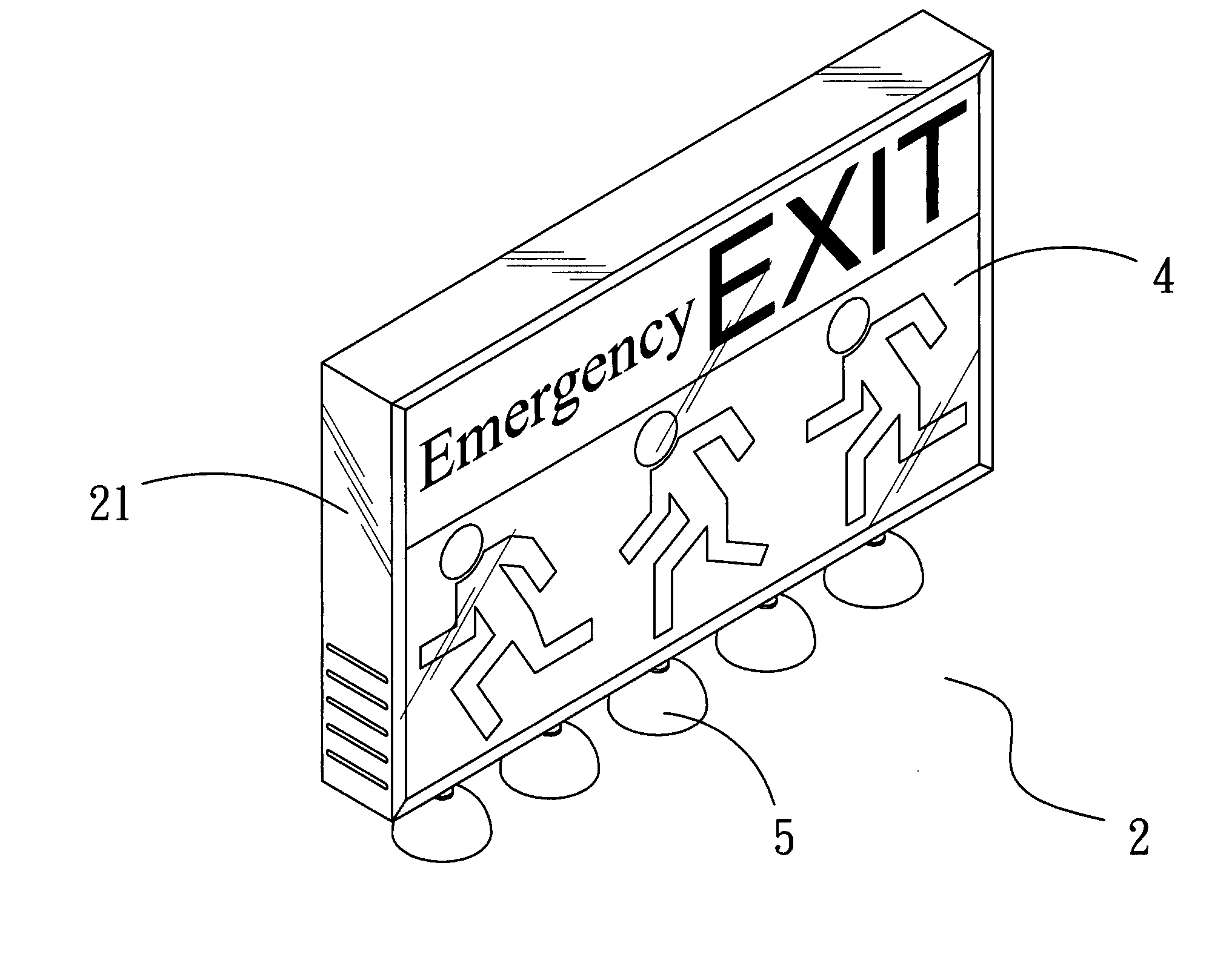
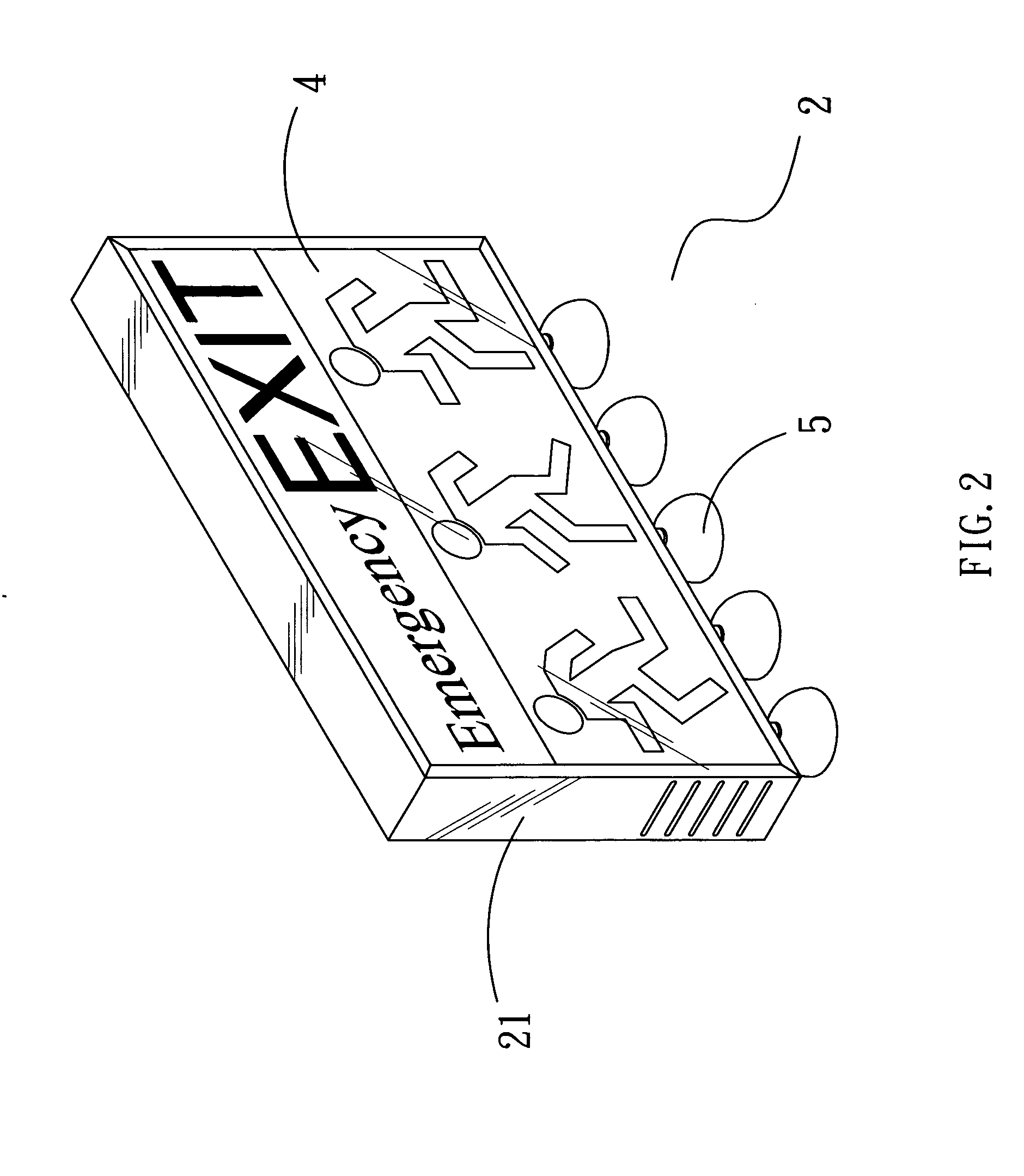
[0019]Referring to FIGS. 2 and 3, a perspective outline view and a perspective exploded view of the present invention are shown therein, respectively. As can be seen clearly from these figures, a dynamic emergency escape indicator 2 primarily comprises a base 21, at least one light emitting device 3, a panel 4, one or more lighting devices 5 and at least one power supply unit 6. The at least one light emitting device 3, which is disposed inside the base 21 along with the at least one power supply unit 6, includes a plurality of light emitting elements 31, which may be light emitting diodes (LEDs), light bulbs, halogen lamps, fluorescent lamps or any other elements that emit light. The indicating panel 4 is formed with a plurality of transparent indicating patterns 41 thereon, and is disposed on one side of the base 21 corresponding to the at least one light emitting device 3 disposed within the base 21. Additionally, each of the one or more lighting devices 5 is connected to an edge...


PUM


Abstract

A dynamic emergency escape indicator primarily comprises a base, at least one light emitting device, a panel, at least one energy storage device and one or more lighting devices. By repeatedly turning on and off the at least one light emitting device in sequence, a plurality of indicating patterns can be presented in sequence continuously, thereby delivering a dynamic indicating effect. Orientations of the lighting devices can be adjusted as needed to illuminate particular objects so as to enhance lighting and guiding effects in case of emergency.

Description

BACKGROUND OF THE INVENTION[0001]1. Technical Field[0002]The present invention relates to a dynamic emergency escape indicator, and more particularly, to an emergency escape indicator capable of providing a dynamic display effect.[0003]2. Description of Related Art[0004]Nowadays, buildings are constructed with an increasingly higher height. On the other hand, a fire, when breaking out, tends to spread very quickly, so people can only escape from the scene of fire in the most primitive way, i.e., walking, within the limited golden time for survival. However, as being lack of air in the initial stage when the fire breaks out, flammable materials in the building typically experience incomplete combustion and give out a massive amount of dense smoke. In this case, if people fail to flee away from the scene of fire immediately, their line of sight will most likely be blocked by the dense smoke, causing difficulty in escaping and even casualty. Therefore, in accordance with relevant statu...

Claims


Application Information

Patent Timeline
Patent Type & Authority Applications(United States)
IPC IPC(8): G08B5/00G09F9/33G09F13/00G08B5/36
CPCG09F13/04G09F2019/225G08B7/062G09F2013/05
Inventor CHEN, JUEI-CHAO
Owner CHEN JUEI CHAO
Why Eureka
Try Eureka