Voltage sag generation device and control method and device for inverter

A generation device and voltage drop technology, applied in the field of mobile power grid, can solve the problems of high stress of switching devices, high purchase price, demanding production process of switching devices, etc.

Active Publication Date: 2013-01-30
CSR ZHUZHOU ELECTRIC LOCOMOTIVE RES INST
View PDF4 Cites 22 Cited by
  • Summary
  • Abstract
  • Description
  • Claims
  • Application Information

AI Technical Summary

Problems solved by technology

[0006] In the VSG of the prior art, when it is necessary to support high-voltage and high-power output, the level must be extended, and a large number of switching devices need to be directly connected in series. This direct series connection method requires high consistency in the turn-on and turn-off of each device. At the same time, it also leads to greater stress on the switching device
Therefore, this also has strict requirements on the production process of the switching device. The purchase price of the currently applicable switching device is very expensive, and the price is as high as hundreds of thousands of dollars, resulting in a high production cost of VSG.

Method used


Image

  • Voltage sag generation device and control method and device for inverter
  • Voltage sag generation device and control method and device for inverter
  • Voltage sag generation device and control method and device for inverter

Examples


Embodiment 1

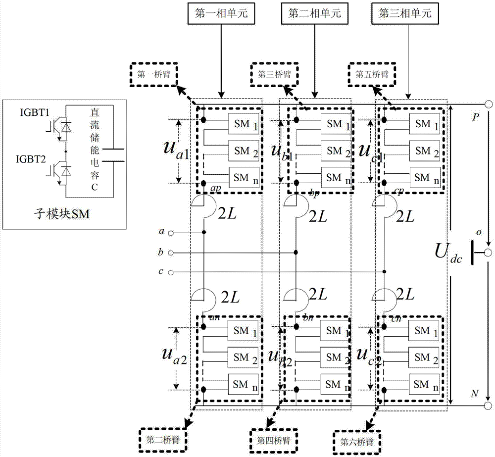
[0073] The present invention provides a voltage drop generating device, the following is the description of Embodiment 1 as an example, please refer to figure 1 , which is a structural schematic diagram of a voltage drop generating device disclosed in Embodiment 1 of the present invention, specifically including:

[0074] Modular multilevel rectifiers and modular multilevel inverters;

[0075] The modular multilevel rectifier and the modular multilevel inverter are connected in a back-to-back power transmission connection, and the modular multilevel inverter has the same structure as the modular multilevel rectifier; in,

[0076] The modular multilevel rectifier includes: a first phase unit formed in series with a first bridge arm and a second bridge arm, a second phase unit formed in series with a third bridge arm and a fourth bridge arm, a fifth bridge arm and a Six bridge arms are connected in series to form the third phase unit, and three phase units are connected in par...

Embodiment 2

[0081] For the devices described in the above embodiments, due to problems such as static and dynamic voltage equalization, electromagnetic interference, and excessive switching losses caused by excessively high switching frequencies, the quality of the voltage drop waveform output by the VSG is not high, and the harmonics The content is large, especially when the number of sub-modules is large, these problems will be more serious. In the prior art, a filter is usually installed on the AC side for filtering, which can eliminate the above problems to a certain extent and avoid affecting the performance of the entire VSG circuit. However, when a filter is installed on the AC side to completely eliminate the AC component of the double frequency, its filtering effect is greatly affected by the frequency. Poor, unable to meet testing requirements.

[0082] In view of the above technical problems, the present invention provides an inverter control method, which controls the modular...

Embodiment 3

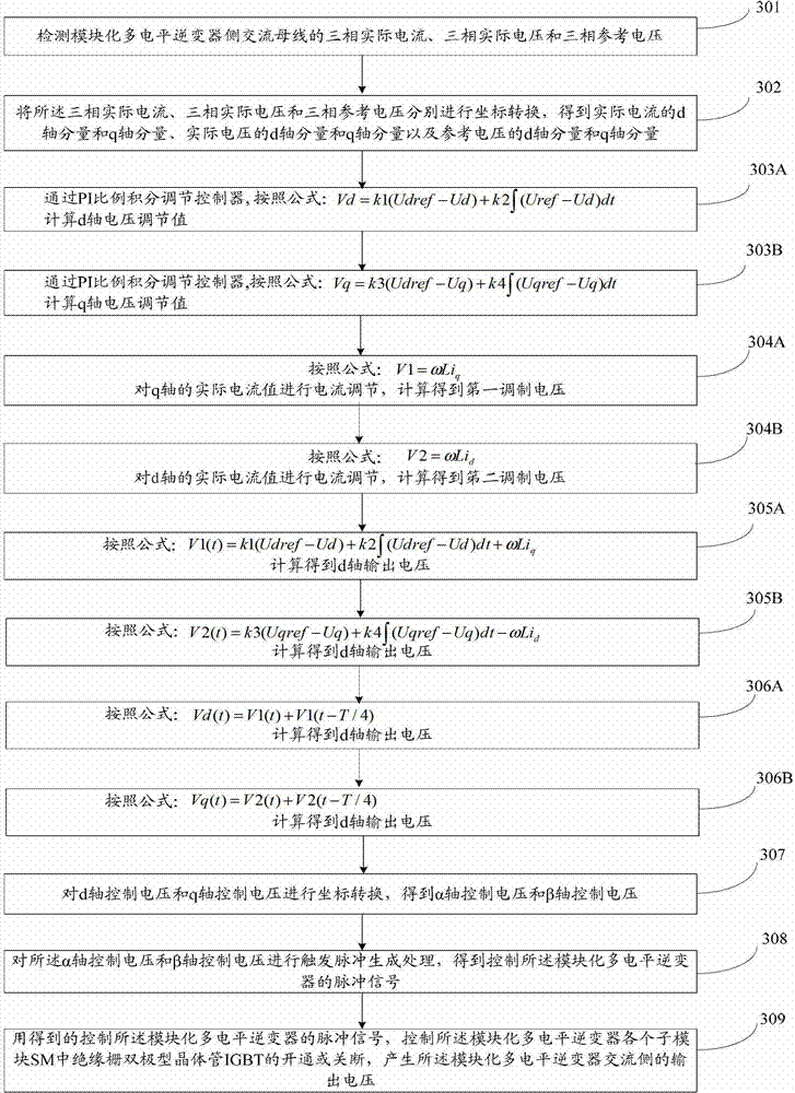
[0094] In order to describe the method proposed by the present invention more specifically, the third embodiment is taken as an example below to describe, for details, please refer to image 3 Another proposed inverter control method is shown in the flow chart, which specifically includes the following steps:

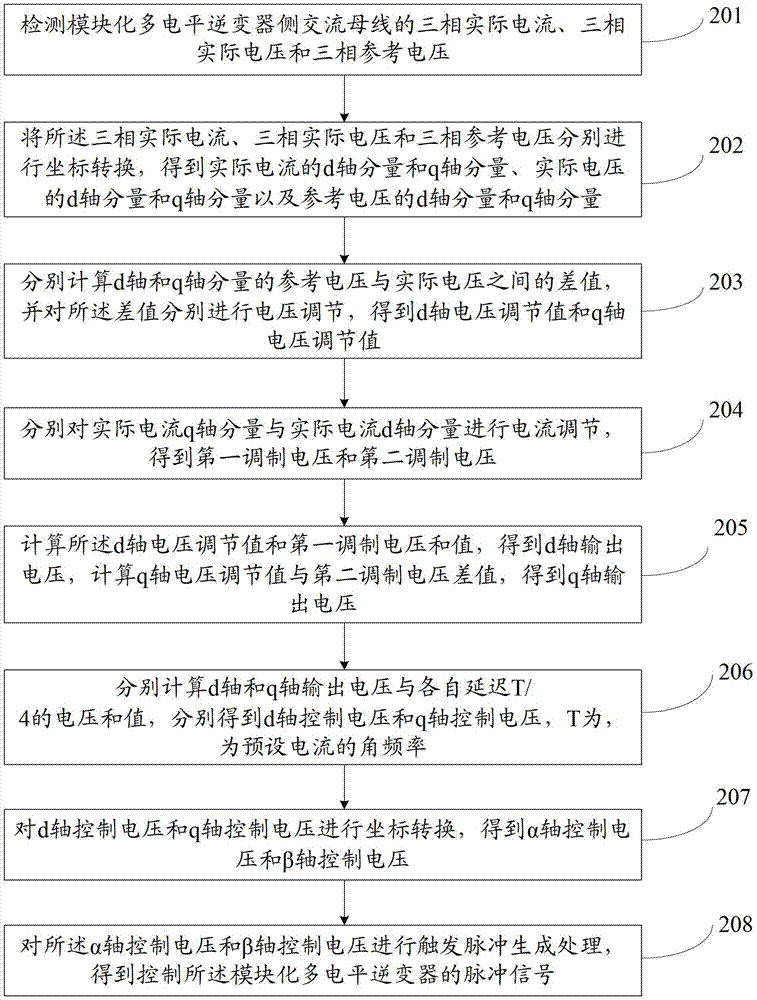
[0095] Step 301: Detect the three-phase actual current, three-phase actual voltage and three-phase reference voltage of the AC bus on the side of the modular multilevel inverter;

[0096] Step 302: Perform coordinate transformation on the three-phase actual current, three-phase actual voltage, and three-phase reference voltage, respectively, to obtain the d-axis component and q-axis component of the actual current, the d-axis component and the q-axis component of the actual voltage, and the reference voltage The d-axis component and q-axis component of ;

[0097] Step 303: Calculate the difference between the reference voltage and the actual voltage of the d-axis and q...


PUM


Abstract

The embodiment of the invention discloses a voltage sag generation device and a control method and a control device for an inverter. The generation device comprises a modular multi-level rectifier and a modular multi-level inverter, wherein the modular multi-level rectifier is connected with the modular multi-level inverter in a back-to-back power transmission connection manner, and the structures of the modular multi-level rectifier and the modular multi-level inverter are the same; each of the modular multi-level rectifier and the modular multi-level inverter comprises three phase units which are connected in parallel with one another; each phase unit consists of two bridge arms which are connected in series with each other; any bridge arm consists of N sub modules SM and a valve reactor which are connected in series; and each SM consists of two insulated gate bipolar transistor (IGBT) switching devices and a direct current energy storage capacitor which are connected in parallel. The device can precisely control a voltage sag depth, lasting time, a phase and a sag type and can be easily expanded to high voltage and high power grade; requirements on high voltage and high power are met; a requirement on the switching devices is low, and the switching devices are easy to purchase; the price is low; an output waveform is relatively high in quality; and the number of filters on an alternating current side is reduced.

Description

technical field [0001] The invention relates to the field of mobile power grids, in particular to a voltage drop generating device, a control method and a device for an inverter. Background technique [0002] As a kind of green renewable energy, wind power has attracted much attention. As the installed capacity of wind turbines accounts for an increasing proportion of the grid, the wind power generation system is connected to the grid through the grid-connected inverter. When the grid fails and the voltage drops to a certain extent, the grid-connected inverter will be disconnected from the grid; The penetration power of wind power generation continues to increase. If a large number of wind power generation systems are disconnected from the grid when the grid fails, it will have a serious impact on the voltage and frequency of the grid, and may even aggravate the degree of failure, eventually leading to the decoupling of all system units. Therefore, the operation ability of ...

Claims


Application Information

Patent Timeline
Patent Type & Authority Applications(China)
IPC IPC(8): H02M5/458H02M7/49
Inventor 张杰李江红王坚应婷谭娟
Owner CSR ZHUZHOU ELECTRIC LOCOMOTIVE RES INST
Why Eureka
Try Eureka