Diffusion plate and backlight module using the same

a technology of diffusion plate and backlight module, which is applied in the direction of lighting device details, lighting and heating apparatus, instruments, etc., can solve the problems of high manufacturing cost, and achieve the effects of reducing costs, increasing production efficiency, and increasing the number of connected diffusion units

Inactive Publication Date: 2009-02-17
INNOCOM TECH (SHENZHEN) CO LTD +1
View PDF13 Cites 21 Cited by
  • Summary
  • Abstract
  • Description
  • Claims
  • Application Information

AI Technical Summary

Benefits of technology

[0009]The number of connected diffusion units may be increased or decreased according to the size of a liquid crystal display to be produced. This eliminates the need to alter the production means for differently sized backlight modules, thereby reducing costs and increasing production efficiency.

Problems solved by technology

Therefore, the cost of manufacture is high when a supplier fills requests for backlight modules of different sizes, especially large sizes.

Method used


Image

  • Diffusion plate and backlight module using the same
  • Diffusion plate and backlight module using the same
  • Diffusion plate and backlight module using the same

Examples


first embodiment

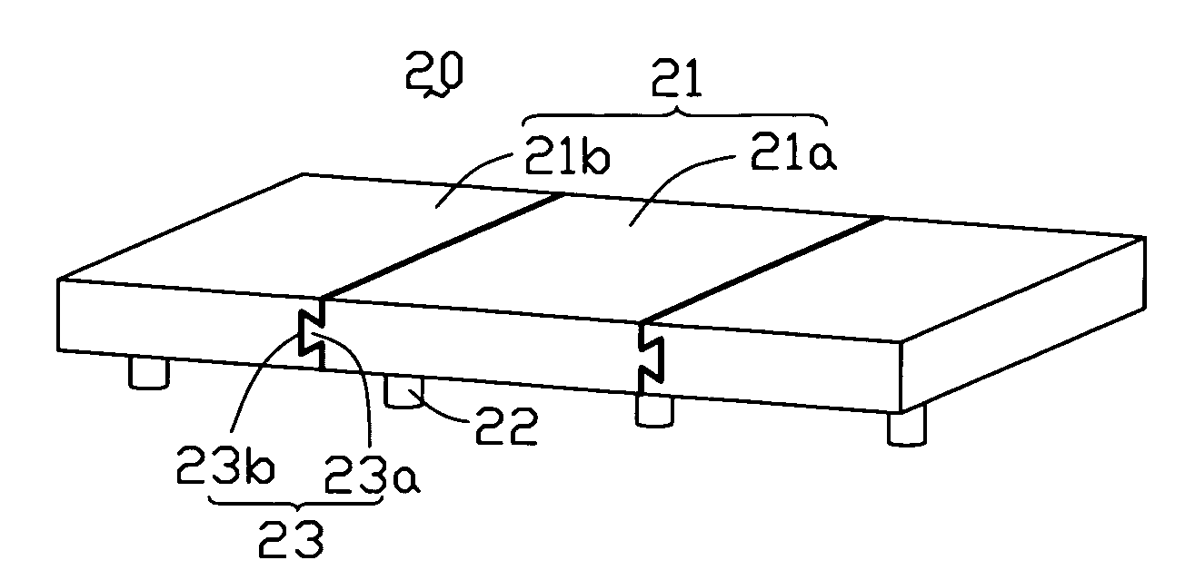
[0018]FIG. 1 is a schematic, isometric view of a diffusion plate 20 according to the present invention. The diffusion plate 20 includes a plurality of diffusion units 21, and a plurality of connecting portions 23 for connecting adjacent diffusion units 21. Each connecting portion 23 comprises either a connection protrusion 23a of a certain shape or a connection slot 23b of a like shape. The connection protrusion 23a of one diffusion unit 21 (such as diffusion unit 21a) is engagingly received in the connection slot 23b of an adjacent diffusion unit 21 (such as diffusion unit 21b). In the illustrated embodiment, the connection protrusion 23a is a dovetail-shaped tenon, the connection slot 23b is a similarly shaped mortise, and the connection protrusion 23a engages in the connection slot 23b to form a joint that connects the diffusion units 21a and 21b firmly together. A plurality of supporting elements 22 are attached to the undersides of the diffusion units 21. The supporting element...

second embodiment

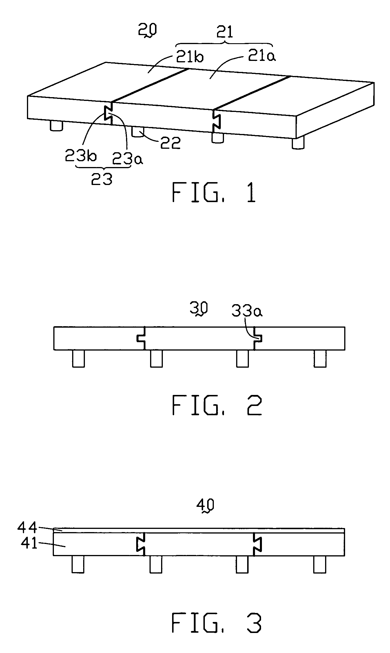
[0020]FIG. 2 is a schematic, side cross-sectional view of a diffusion plate 30 according to the present invention. The diffusion plate 30 is similar to the diffusion plate 20 of FIG. 1. However, each of connection protrusions 33a and each of corresponding connection slots (not labeled) defines a rectangular profile.

third embodiment

[0021]FIG. 3 is a schematic, side cross-sectional view of a diffusion plate 40 according to the present invention. The diffusion plate 40 is similar to the diffusion plate 20 of FIG. 1. However, a layer of oxide 44 is provided on top surfaces of diffusion units 41. The layer of oxide 44 can compensate color hue of light beams passing through the diffusion units 41, and can avoid generation of bright or dark lines at the joints of adjacent diffusion units 41.


PUM


Abstract

A diffusion plate (20) includes at least two diffusion units (21), each diffusion unit including at least one connecting portion (23). The connecting portions (23a, 23b) of each two adjacent diffusion units mate with each other, thereby connecting all the diffusion units together. The number of diffusion units may be increased or decreased according to the size of a liquid crystal display to be produced. This eliminates the need to alter the production means for differently sized backlight modules, thereby reducing costs and increasing production efficiency. In another embodiment, a diffusion plate (50) includes at least two diffusion units (51). Each diffusion unit includes at least one connection protrusion (53a). At least one interconnecting member (53) is disposed between each two adjacent diffusion units. The interconnecting member and the connecting protrusions mate with each other, thereby connecting all the diffusion units together. A related backlight module (500) is also provided.

Description

FIELD OF THE INVENTION[0001]The present invention relates to diffusion plates for backlight modules, and more particularly to a diffusion plate formed by the interconnection of diffusion units.GENERAL BACKGROUND[0002]With the widespread use of liquid crystal display devices, such as in high-end portable electronic devices, mobile phones, and PDAs (Personal Digital Assistants), and more particularly for large size LCD TVs, there is a demand for large size diffusion plates and backlight modules.[0003]As shown in FIG. 7, a typical diffusion plate 10 includes a transparent substrate 11 and a diffusion layer 12 disposed on a surface of the transparent substrate 11. The diffusion layer 12 includes a transparent main portion 13, and a plurality of light diffusion particles 14 embedded in the main portion 13.[0004]However, the production means for the above-mentioned typical diffusion plate 10 must be altered for each unique size requirement of a corresponding backlight module. Therefore, t...

Claims


Application Information

Patent Timeline
Patent Type & Authority Patents(United States)
IPC IPC(8): F21V5/00
CPCG02B5/0242G02B5/0278G02F1/133606G02F2201/465
Inventor FANG, WU-HONGHUANG, YU-LIANG
Owner INNOCOM TECH (SHENZHEN) CO LTD
Why Eureka
Try Eureka