Antenna beam scan unit and wireless communication system using antenna beam scan unit

a technology of wireless communication system and beam scan unit, which is applied in the direction of digital transmission, antennas, electrical apparatus, etc., can solve the problems of no effect, degrading communication quality, and difficulty in realizing power division and synthesis

Active Publication Date: 2012-10-11
KOKUSA ELECTRIC CO LTD
View PDF0 Cites 25 Cited by
  • Summary
  • Abstract
  • Description
  • Claims
  • Application Information

AI Technical Summary

Benefits of technology

[0014]According to the present invention, there is provided an antenna beam scan unit capable of offering an antenna gain in a desired direction and narrowing an antenna beam angle without an increase in the number of input beams, and a wireless communication system using the antenna beam scan unit.

Problems solved by technology

However, in case an obstacle approaches the target entity, the obstacle and target entity often exist within the range of one beam.
However, widening a beam angle invites degradation of communication quality in a space in which multipath propagation occurs frequently.
However, since a transmission signal is subjected to spatial synthesis, electromagnetic waves reach an obstacle therefore no effect is exerted in suppression of multipath propagation.
However, when multipath propagation occurs, a narrower-angle antenna has to be used for scanning.
There is difficulty in realizing power division and synthesis for an antenna element in an antenna structure having a beamforming feature, and increasing or decreasing the number of effective antenna elements at the same time.
In particular, when an obstacle exists near a target entity, a communication failure due to multipath propagation occurs because of waves reflected from the obstacle.
However, the configuration of a beamforming device gets more complex.

Method used


Image

  • Antenna beam scan unit and wireless communication system using antenna beam scan unit
  • Antenna beam scan unit and wireless communication system using antenna beam scan unit
  • Antenna beam scan unit and wireless communication system using antenna beam scan unit

Examples


first embodiment

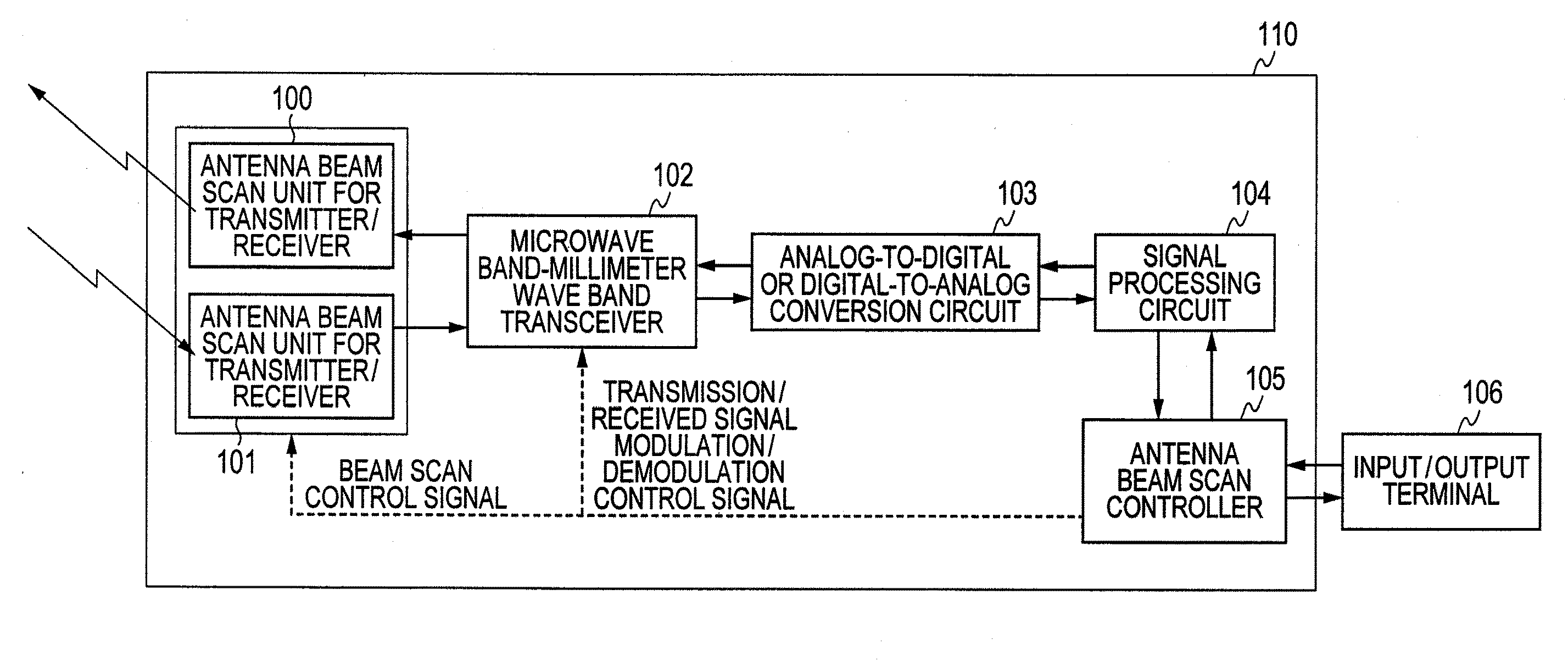
[0034]A wireless communication system using a millimeter-wave antenna beam scan unit which is a first embodiment of the present invention will be described in conjunction with FIG. 1 to FIG. 8C.

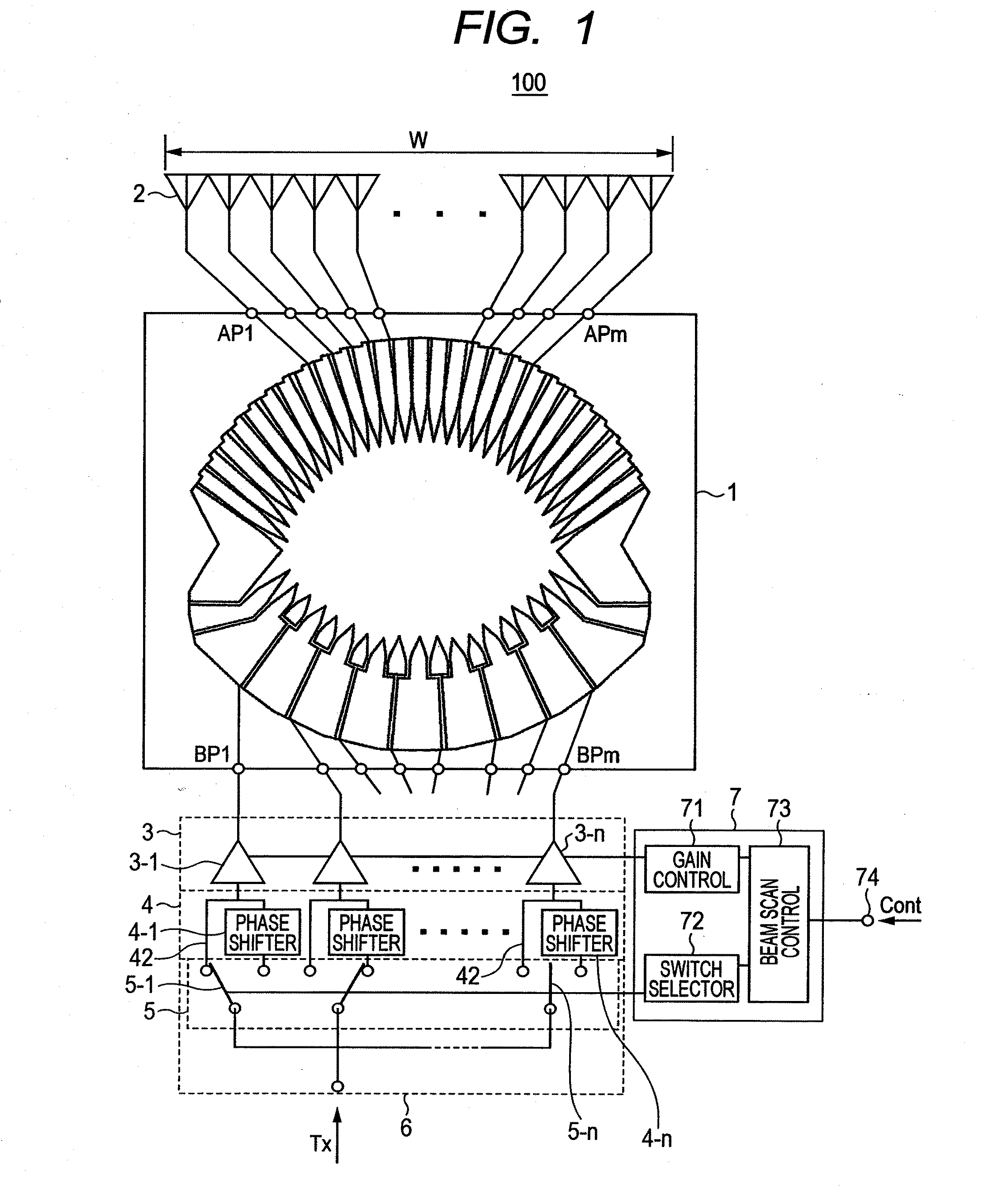
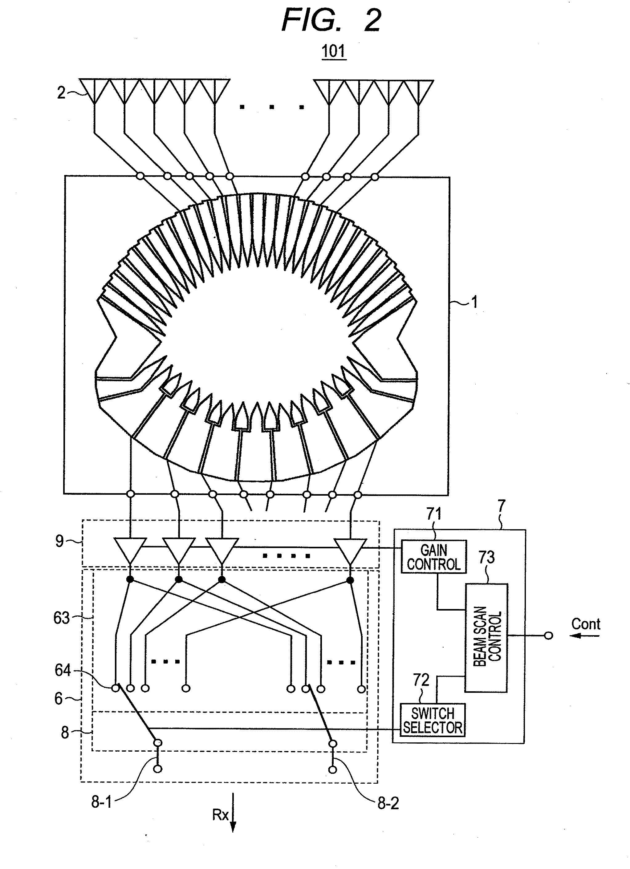
[0035]To begin with, referring to FIG. 1, the configuration of a phased array antenna beam scan unit for transmitter 100 using a Rotman lens in accordance with the present embodiment will be described below. In FIG. 1, there are shown a Rotman lens 1, antenna elements 2, variable amplifiers 3 (3-1 to 3-n), and input blocks 4. The Rotman lens 1 includes plural input and output ports, that is, antenna ports (AP1 to APm) and beam ports (BP1 to BPn). The antenna elements 2 to or from which radio waves are inputted or outputted are connected to the antenna ports. The variable amplifiers 3 capable of performing amplitude modulation on a signal are connected to the respective ones of the other beam ports. That is, the number of variable amplifiers is identical to the number of beam ports (three or m...

second embodiment

[0054]FIG. 9 shows a second embodiment of an antenna beam scan unit of the present invention. There are shown a Rotman lens 1, antenna elements 2, variable amplifiers 3, fixed phase shifters 4, switches 5, a splitter 60, and a multi-port switch 8.

[0055]The Rotman lens shown in FIG. 9 is also an example including twelve antenna ports and eight beam ports. The antenna elements 2 are connected to the respective antenna ports of the Rotman lens 1, and the output terminals of the variable amplifiers 3 capable of performing amplitude modulation are connected to the respective beam ports. As input blocks 4 of the variable amplifiers 3, similarly to those in the first embodiment, the fixed phase shifters 41 that serve as second paths intended to indicate a null point when radio waves are radiated from the antenna elements 2 via the Rotman lens 1, and through paths 42 that are first paths intended to keep waves, which are inputted to adjoining beam ports, in phase with each other are connect...

third embodiment

[0057]FIG. 10 shows a third embodiment of an antenna beam scan unit of the present invention. There are shown a Rotman lens 1, antenna elements 2, variable amplifiers 3, a group of fixed phase shifters 4, switches 5, a splitter 60, and a multi-port switch 8.

[0058]The Rotman lens 1 shown in FIG. 10 is an example having twelve antenna ports and eight beam ports. The antenna elements 2 are connected to the respective antenna ports of the Rotman lens, and the output terminals of the variable amplifiers 3 capable of performing amplitude modulation are connected to the respective beam ports. As an input block of each of the variable amplifiers 3, the fixed phase shifters are connected to two input terminals thereof. The group of fixed phase shifters 4 has difficulty in forming a transmission path on which no phase difference is given in a millimeter-wave band. As first paths on which no phase difference is given and second paths on which a signal that is out of phase with a signal on the ...


PUM


Abstract

An antenna beam scan unit includes: a Rotman lens that performs power division and synthesis between plural antenna ports and three or more beam ports; plural antenna elements which are connected to the respective antenna ports and to or from which radio waves are inputted or outputted; plural amplifiers that are connected to the respective beam ports of the Rotman lens and perform amplitude modulation on a signal; input paths for a transmission signal disposed in association with the amplifiers; switches for switching the input paths; and a beam control unit. The input paths include first paths and second paths on which a signal that is out of phase with a signal on the first paths is produced. The beam control unit selects two adjoining beam ports, and can switch the first paths and second paths as the input paths for the two beam ports.

Description

CLAIM OF PRIORITY[0001]The present application claims priority from Japanese Patent Application JP 2011-084838 filed on Apr. 6, 2011, the content of which is hereby incorporated by reference into this application.FIELD OF THE INVENTION[0002]The present invention relates to an antenna beam scan unit and a wireless communication system using the antenna beam scan unit. More particularly, the present invention is concerned with an antenna unit that uses a Rotman lens to perform phase synthesis and division.BACKGROUND OF THE INVENTION[0003]In case an obstacle with high reflection intensity (a truck, a guardrail, a shutter, a refrigerator, or the like) is present in the vicinity of a target entity such as communication equipment, electromagnetic interference occurs due to multipath propagation. This degrades communication quality. A phased-array antenna is known as a technology for transmitting or receiving electromagnetic waves selectively in a specific direction by sweeping a narrow-an...

Claims


Application Information

Patent Timeline
Patent Type & Authority Applications(United States)
IPC IPC(8): H04B1/38H01Q3/00
CPCH01Q3/2682
Inventor NAGAISHI, HIDEYUKISHIBAGAKI, NOBUHIKOSHIMAYAMA, YUICHI
Owner KOKUSA ELECTRIC CO LTD
Why Eureka
Try Eureka