Method for Removal of Bone

a bone and talus technology, applied in the field of orthopaedics, can solve the problems of sacrificing the anterior cortex, removing too much bone, and difficult to do, and achieve the effect of removing the chance of anterior cortex fracturing, accurate and repeatable keel slots, and reducing the chance of fractur

Inactive Publication Date: 2010-01-28
DEPUY SYNTHES PROD INC
View PDF101 Cites 27 Cited by
  • Summary
  • Abstract
  • Description
  • Claims
  • Application Information

AI Technical Summary

Benefits of technology

This patent describes a new method for removing burs or other abnormal tissue growths during spine surgeries. One key benefit is that it uses a special tool called a burr guider that allows for easier removal of these growths while preserving important parts of the patient's body such as the front part of the lower jaw (the mandible). Additionally, the method can provide more precise and consistent results compared to traditional methods used by experienced surgeons. Overall, this technology makes surgeries safer and faster, reducing recovery time and improving patient satisfaction.

Problems solved by technology

This patent discusses the technical problem of replacing damaged ankle joints through prosthetic devices. However, there are challenges related to restoring the functionality of the original joint while ensuring proper alignment, matching the load-bearing requirements, ease of installation, durability, etc. Additionally, existing methods involve relying on skilled surgeons and may compromise the quality of the repair. Therefore, this patent proposes an improved instrumentation system and surgical procedure to address these issues and enhance the precision and reliability of ankle joint replacement procedures.

Method used


Image

  • Method for Removal of Bone
  • Method for Removal of Bone
  • Method for Removal of Bone

Examples


Embodiment Construction

[0048]Embodiments of the present invention and the advantages thereof are best understood by referring to the following descriptions and drawings, wherein like numerals are used for like and corresponding parts of the drawings.

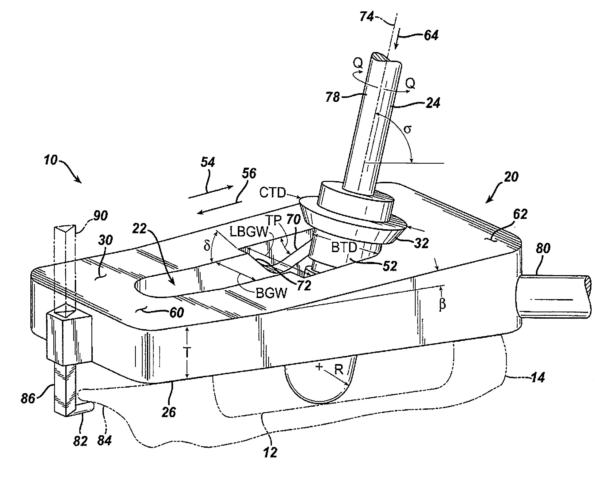
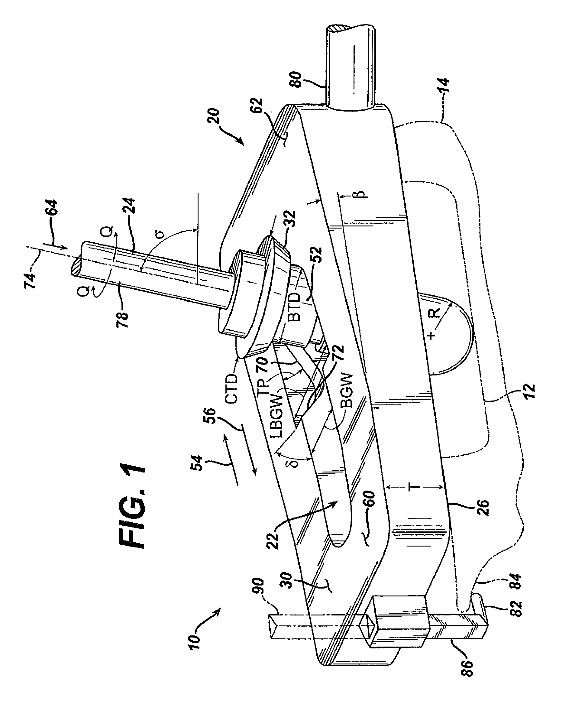
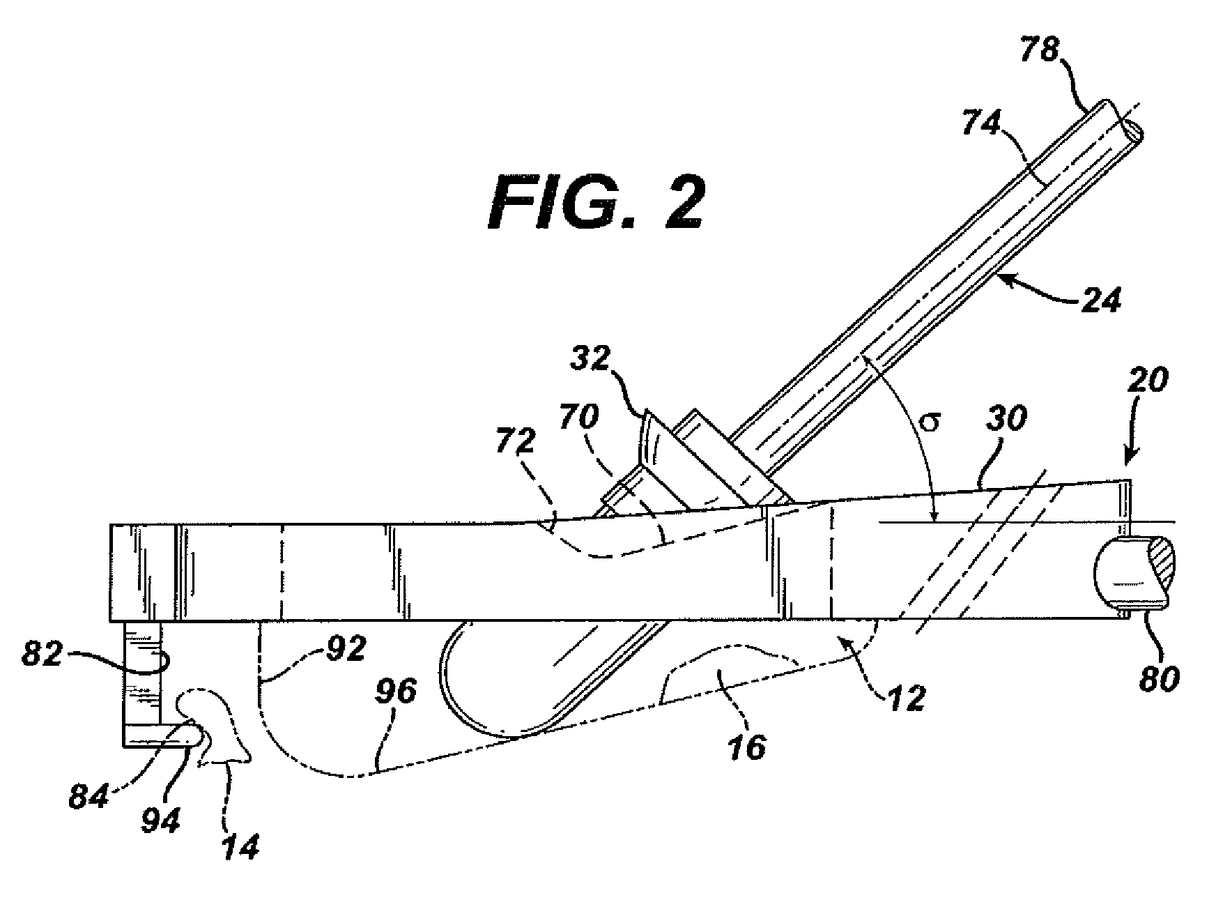
[0049]According to the present invention and referring now to FIG. 1, an embodiment of the present invention is shown as kit 10. Kit 10 is utilized for preparation of bone cavity 12 for implementation of a joint prosthesis (see FIGS. 19-21). The kit 10 includes a guide 20 which defines an opening 22 through the guide 20. The kit 10 further includes a rotatable tool 24 adapted to be constrainable within the opening 22 of the guide 20. The tool 24 is adapted for removal of bone 14 to form the bone cavity 12.

[0050]The guide 20 may define a first surface 26 of the guide 20 for cooperation with the bone 14. The guide 20 may also include a second surface 30 which is spaced from and may be parallel to the first surface 26. The tool 24 may include a collar 32 for coop...


PUM


Abstract

A kit (10) for preparation of a bone cavity (12) in a bone (14) for implantation of a joint prosthesis (16) is provided. The kit (10) includes a guide (20) defining an opening (22) therethrough. The guide (20) is in cooperation with the prosthesis. The kit (10) also includes a rotatable tool (24) constrainable within the opening (22) of said guide (20). The tool (24) is adapted for removal of bone (14) to form the bone cavity (12).

Description


Claims


Application Information

Patent Timeline
Owner DEPUY SYNTHES PROD INC
Why Eureka
Try Eureka