In-bone implantable shaft for prosthetic joints or for direct skeletal attachment of external limb prostheses and method of its installation

Inactive Publication Date: 2009-03-05
PITKIN MARK
View PDF38 Cites 9 Cited by
  • Summary
  • Abstract
  • Description
  • Claims
  • Application Information

AI Technical Summary

Benefits of technology

[0017]The present invention relates to the creation of favorable conditions for the ingrowth of bone cells and tissues between and throughout the sides of the implanted shaft (“osseolocking”). To increase the positive effect of osseolocking, the bone walls are specially prepared in conjunction with the standard drilling of the medullary canal. That specific preparation includes fashioning one or more slots in t

Problems solved by technology

One of the major problems involved in the use of such devices is the loosening of the attachment between the prosthetic implant and the associated bone.
One of the reasons for loosening, after all these approaches or their several combinations are used, is that the approaches are all in conflict with the stru

Method used


Image

  • In-bone implantable shaft for prosthetic joints or for direct skeletal  attachment of external limb prostheses and method of its installation
  • In-bone implantable shaft for prosthetic joints or for direct skeletal  attachment of external limb prostheses and method of its installation
  • In-bone implantable shaft for prosthetic joints or for direct skeletal  attachment of external limb prostheses and method of its installation

Examples


Embodiment Construction

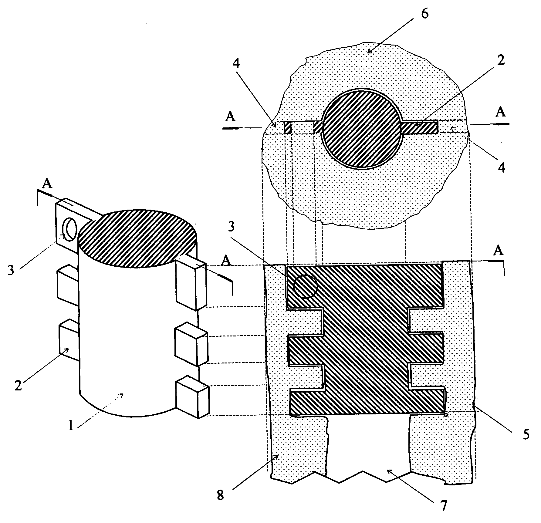
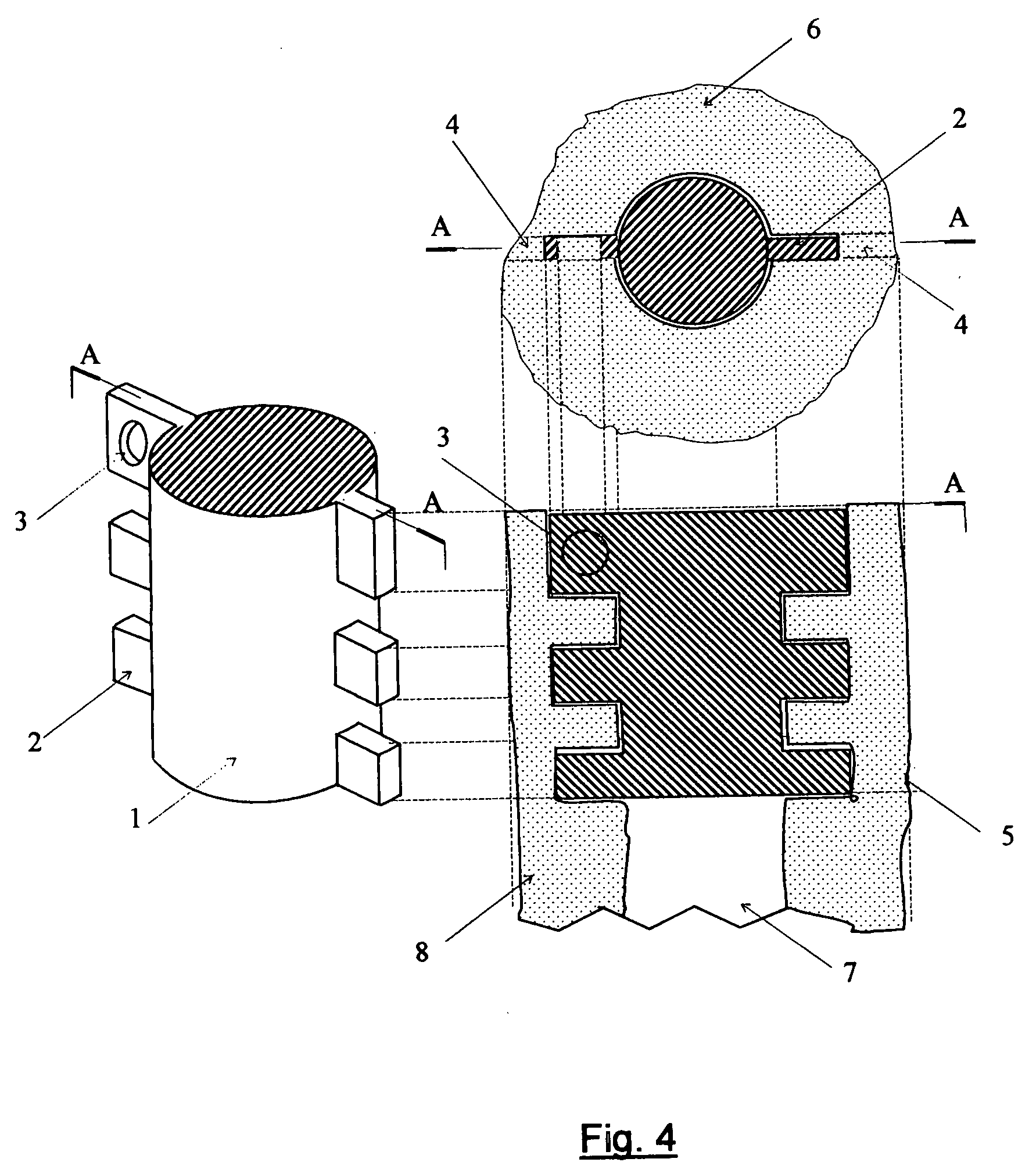
[0022]The device in the present invention, namely, the implantable shaft of the prosthetic joint or the abutment for the attachment of an external limb prosthesis, has a central portion 1 situated in the cavity of the medullary canal 7 of the bone 6. The side elements 2 of this device are situated in the slots 4 pre-cut out of the walls 8 of the bone.

[0023]The method of installation of the device is also a component of the present invention, and is implemented once the marrow cavity of the bone in which implantation is planned is prepared in the conventional manner (by drilling a cavity in the medullary canal 7). Specifically, a guide 9 with slots 4 (see FIG. 5) is inserted into a pre-drilled cavity in the medullary canal 7. The diameter of the drill that prepares the cylindrical cavity has to correspond to the diameter of the cavity and the depth of drilling should correspond to the height of the shaft 1 to allow the guide to be easily inserted and removed manually without addition...


PUM


Abstract

An in-bone implantable shaft for prosthetic joints or for direct skeletal attachment of external limb prostheses, comprised of a central body fitted in the zone of the bone's medullary cavity conventionally prepared for implantation, and of side elements attached to the central body and fitted in the slots specially made in the bone's walls surrounding said medullary canal; said side elements have spaces between them, arranged to be filled by bone cells to provide a natural and safe osseolocking of the shaft. A method of preparing the bone for implantation of a prosthetic shaft, comprising the steps of: placing a cylindrical guide with slots made in the longitudinal direction of said guide inside said bone's canal which is conventionally prepared for implantation; cutting said bone's walls by progressing a saw along the edges of the slots of said guide; removing the guide; fitting the shaft in the bone's canal, provided that the side elements are fitted to the slots in the bone's walls.

Description

TECHNICAL FIELD[0001]Prosthetics, surgical instruments; more particularly, methods and devices for surgically preparing a bone for the implantation of a prosthetic implant component of a prosthetic joint [1, 2] or the implantation of an abutment for direct skeletal attachment of external prostheses, as described in: http: / / www.sahlgrenska.se / vgrtemplates / Page—33031.aspx.BACKGROUND OF THE INVENTION[0002]This invention relates to prosthetic implants for skeletal replacement, reconstruction and attachment in humans and animals, and, more particularly, to the design and method of installation of such devices that would reduce their loosening with time.[0003]Implantable devices are used to partially or completely replace joints or bone segments in humans and animals, or to provide direct skeletal attachment of external prostheses to the residuum.[0004]The known approaches to attaching the implants include fitting the implant into the medullary canal of the bone by force; securing the imp...

Claims


Application Information

Patent Timeline
IPC IPC(8): A61F2/60
CPCA61B17/15A61F2/28A61F2/30721A61F2/30749A61F2/78A61F2002/30434A61F2002/30848A61F2002/30884A61F2002/30892A61F2002/30899A61F2002/7887A61F2220/0041A61F2/30A61F2/4644A61L2430/02A61B17/7258A61F2002/30433A61F2002/30845
Inventor PITKIN, MARK
Owner PITKIN MARK
Why Eureka
Try Eureka