Support structure implant for a bone cavity

A technology for supporting structures and implants, used in bone implants, braids, internal bone synthesis, etc., to solve problems such as spinal structure collapse

Inactive Publication Date: 2012-04-11
DUPUY INT LTD
View PDF14 Cites 7 Cited by
  • Summary
  • Abstract
  • Description
  • Claims
  • Application Information

AI Technical Summary

Problems solved by technology

which can lead to collapse of the spinal structure

Method used


Image

  • Support structure implant for a bone cavity
  • Support structure implant for a bone cavity
  • Support structure implant for a bone cavity

Examples


Embodiment Construction

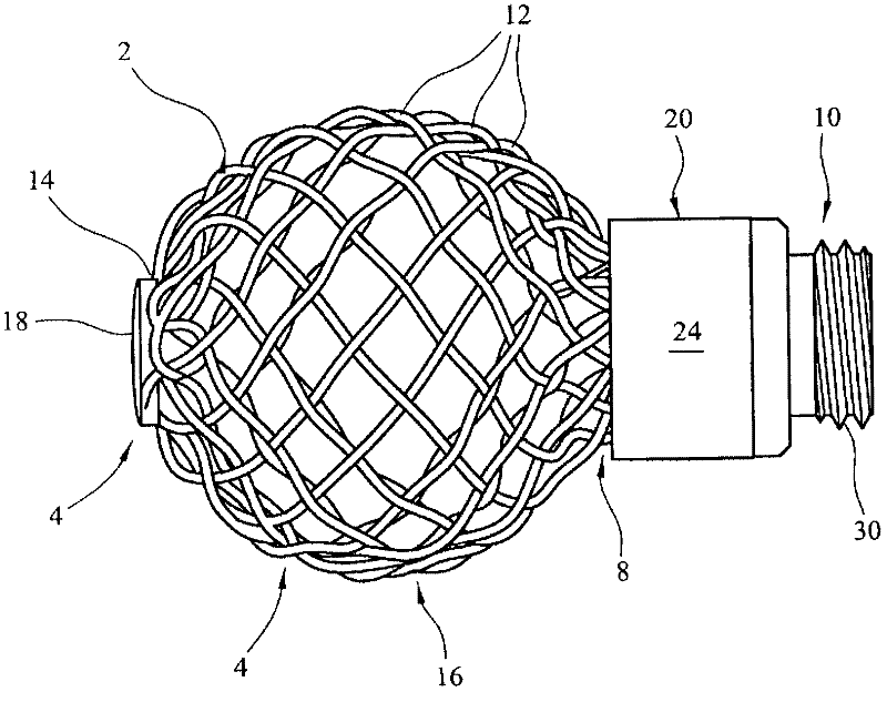
[0084] With reference to the accompanying drawings, figure 1 A stranded support structure implant 2 is shown, which can be implanted in a cavity of bone to support the bone defining the cavity. The implant has a circular spherical portion 4 at a first end 6 of the implant, and a cylindrical throat portion 8 at a second end 10 of the implant.

[0085] The implant 2 is formed from twelve wires 12 formed from a nickel-titanium shape memory alloy which has been treated so that it exhibits enhanced elasticity. The wire has a diameter of 0.5 mm.

[0086] Each wire forms a coil 14 . The coils are collected together on the first end 6 of the implant such that two lengths of each wire extend from the first end. Thus extending from the first end of the implant are 24 lengths of wire, which are braided. The bulbous portion 4 is configured such that the implant expands outwardly from the first end 6 towards the broad point 16 and tapers inwardly from the broad point towards the throat...


PUM


Abstract

support structure implant for location within a bone cavity to support the bone which defines the cavity is formed from wires by braiding in a machine direction from a first end of the structure towards an opposite second end. The wires are formed into loops at the first end of the structure so that two lengths of wire extend away from each loop and a reformed into the braid. Each of the wires which is formed into the braid is held at the second end of the structure in a clamp. The clamp is provided by a support ring and a clamp ring which is formed from a shape memory alloy which can shrink to clamp the wires against the support ring when heated.

Description

technical field [0001] The present invention relates to a support structure implant positionable within a bone cavity to support the bone defining the cavity. It also relates to an assembly for deploying a stranded support structure implant in a bone cavity. Background technique [0002] Cavities may form in bones as a result of disease, or as a result of trauma, or as a result of surgery. Treatment for this condition may involve supporting the cavity as bone tissue regenerates within the cavity. Filling material may be provided in the cavity. This may be a curable material such as an acrylate material similar to that used as bone cement to secure the joint prosthetic components. It may be a material that stimulates regeneration of bone tissue, such as granulated bone tissue. [0003] Avascular necrosis (AVN), also known as osteonecrosis (ON), ischemic osteonecrosis, or aseptic necrosis, results from temporary or permanent loss of circulation to bone tissue and results i...

Claims


Application Information

Patent Timeline
Patent Type & Authority Applications(China)
IPC IPC(8): A61B17/88
CPCA61B17/7098D04C3/48D10B2509/00A61B17/8858A61B17/68D04C1/06A61F2/28A61B17/88
Inventor J·安德森I·格林G·穆尔
Owner DUPUY INT LTD
Why Eureka
Try Eureka