Baler and wrapper combination

a technology applied in the field of baler and wrapper combination, can solve the problems of large amount of time, and large amount of time, and achieve the effect of wrapper, and reducing the number of baler

Active Publication Date: 2010-02-04
DEERE & CO
View PDF10 Cites 30 Cited by
  • Summary
  • Abstract
  • Description
  • Claims
  • Application Information

AI Technical Summary

Benefits of technology

[0010]Accordingly, a baler and wrapper combination is arranged to be pulled behind a tractor over a field and comprises baler and a wrapper, as well as a bale transport table. The bale transport table is movable in the fore-aft direction of the combination, between a bale receiving position in which it can receive a completed bale that is ejected by the baler, and a wrapping position in which the wrapper can wind sheet material around the bale, while the latter is rotated around its central horizontal axis by movable bale support elements of the bale transport table. Further, the bale support table is movable into a bale depositing position in which the wrapped bale is deposited onto the ground. The bale support elements are arranged to be moved, in the bale depositing position, into an orientation in which the bale is deposited on its flat end. Preferably, they can also be moved into an orientation in which the bale is deposited on its circumference. The former position has the advantage that the bale cannot roll away, especially on sloped fields.
[0013]The first mentioned orientation and also the latter one can be achieved when the bale support elements are arranged to be rotationally driven around a vertical axis. Such a rotational mounting of the bale support elements allows selecting the orientation of the bale transport table and thus the bale in the bale depositing position before and / or during unloading between a position in which the bale is deposited on its circumference, and by turning the bale transport table by up to 900 around the vertical axis, another position in which the bale is deposited on its flat end.
[0017]Between the bale transport table support element and the bale transport table, at least one wheel can be provided for reducing the friction. Preferably, a single wheel is mounted to the bale transport table for this purpose, although it would be possible to mount two or more wheels to the bale transport table or to the bale transport table support element.

Problems solved by technology

One disadvantage of the separate wrappers is that a tractor and an operator are required for a second operation in the field after baling, and that a considerable amount of time can pass before the bale is wrapped, such that the crop may wilt or spoil in the meantime.
One disadvantage of the wrapper pulled behind the baler is that the entire combination is relatively long and thus difficult to operate in a field, especially during turning in the headland and in particular when heading backwards.
Another problem, both with the known wrappers pulled behind the baler and the baler / wrapper combinations having a single frame, is that if the bale is to be deposited on its flat end, additional tilting devices need to be employed for tipping the bale over during unloading, adding complexity and cost to the machine.

Method used


Image

  • Baler and wrapper combination
  • Baler and wrapper combination
  • Baler and wrapper combination

Examples


Embodiment Construction

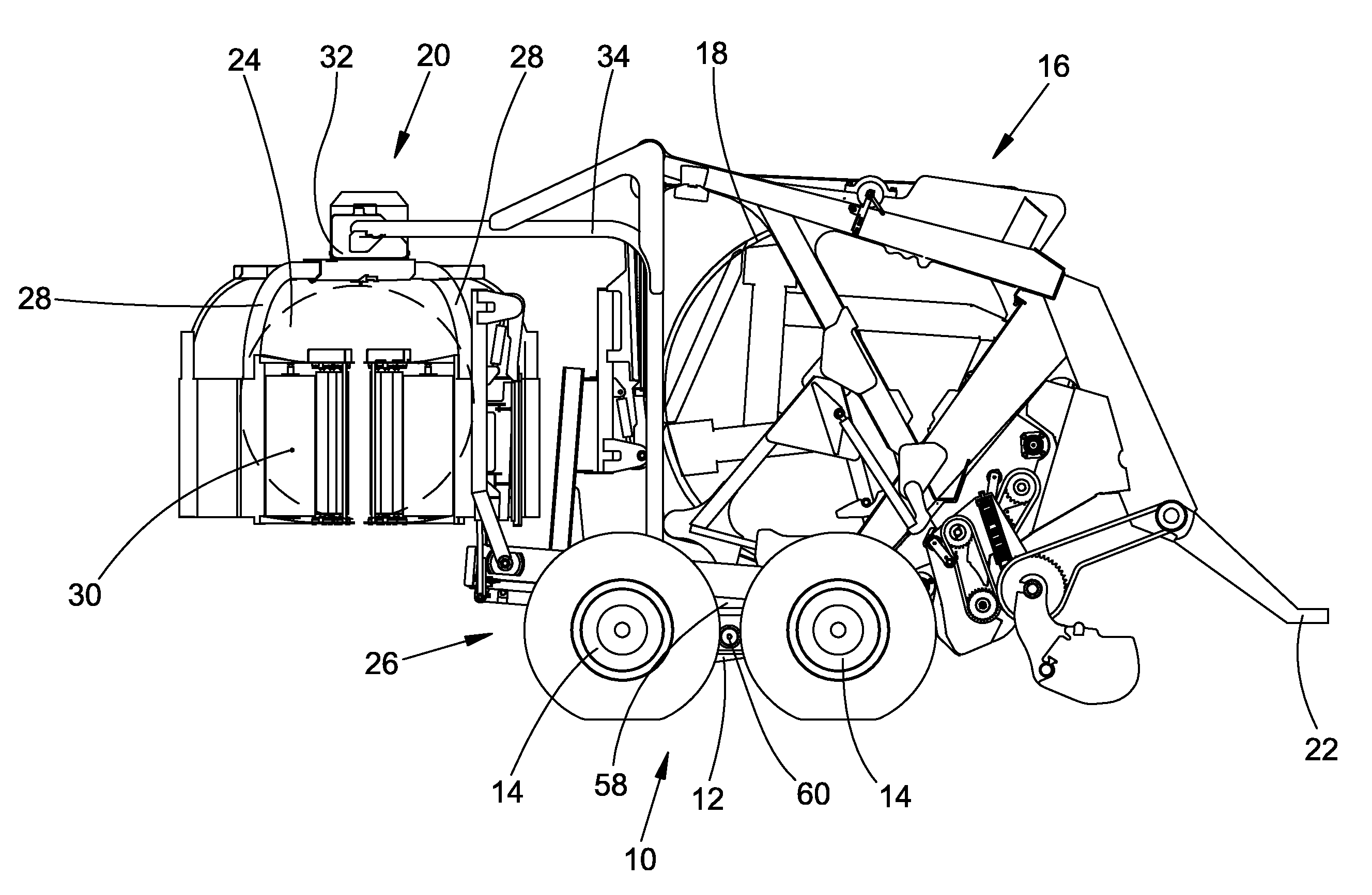
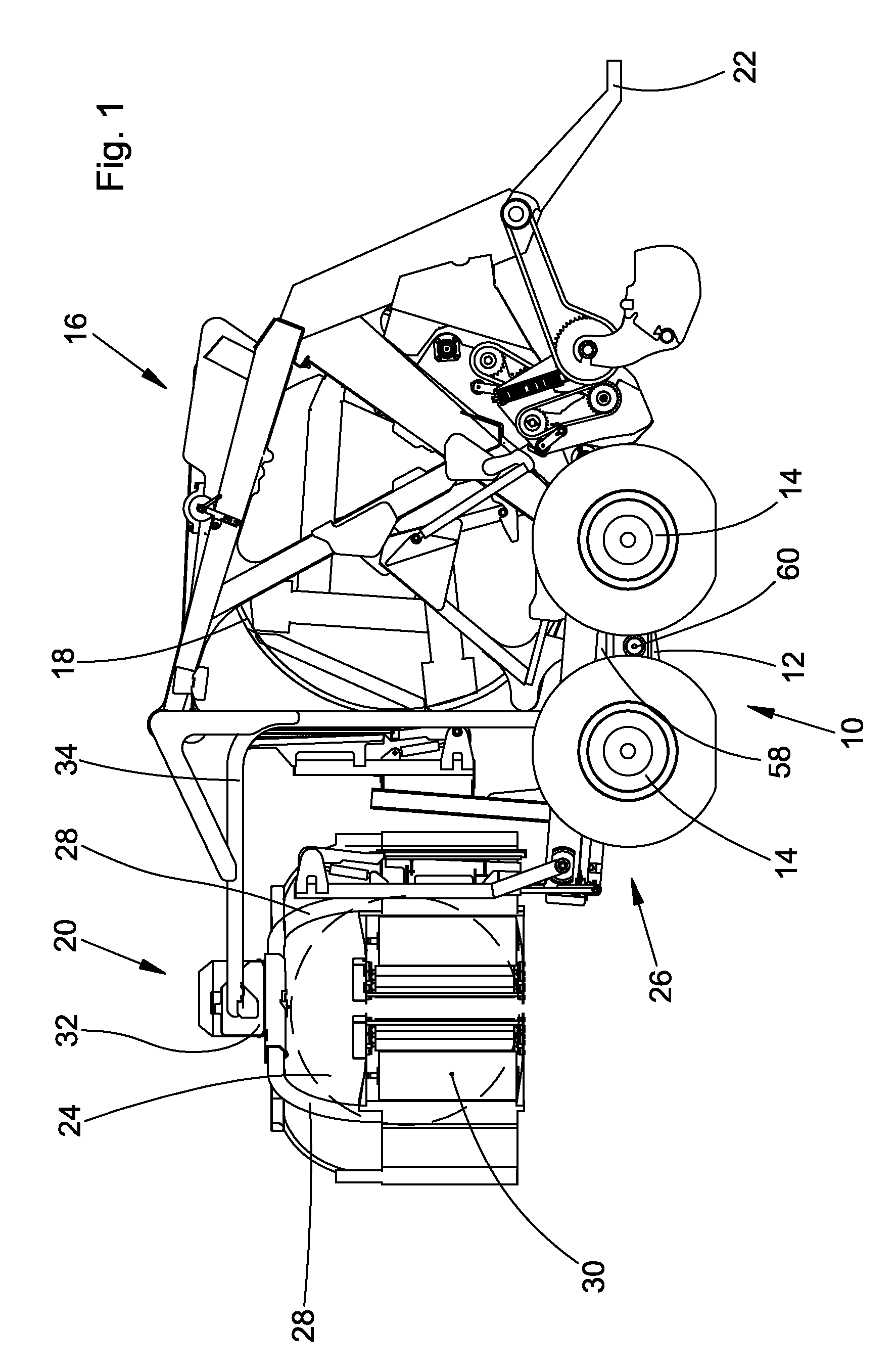
[0033]FIG. 1 is an elevational view of the right side of a baler and wrapper combination 10. The baler and wrapper combination 10 comprises a single frame 12 supported on tandem wheels 14. The frame 12 supports a baler 16 with a rear door 18 and a bale wrapper 20. In operation the baler and wrapper combination 10 is pulled behind a tractor (not shown) by a tongue 22 into a forward direction that extends in FIG. 1 to the right side. The baler and wrapper combination 10 could also be a self-propelled unit, manned or unmanned.

[0034]A bale 24 produced in the baler 16 is transported by a movable bale transport table 26 (not shown in FIG. 1, since in the bale receiving position below the rear door 18, but shown in the following figures) from a bale receiving position at a bale output location beneath the rear door 18 of the baler 16 to a wrapping position beneath the bale wrapper 20. Above the bale transport table 26 in the wrapping position, two opposite arms 28 having orthogonal vertica...


PUM

PropertyMeasurementUnit
angleaaaaaaaaaa
circumferenceaaaaaaaaaa
timeaaaaaaaaaa

Abstract

A baler and wrapper combination comprises a baler, a bale wrapper, and a bale transport table. The bale transport table is movable between a bale receiving position at a bale output location of the baler, a wrapping position at which the wrapper can wrap a bale located upon the bale transport table with a sheet material, while movable bale support elements rotate the bale around its horizontal central axis, and a bale depositing position in which a wrapped bale can be deposited on the ground. The bale support elements are arranged to be moved in the bale depositing position into an orientation in which the bale is deposited on its flat end.

Description

FIELD OF THE INVENTION[0001]The present invention relates to a baler and wrapper combination. The baler and wrapper combination has a baler, a bale wrapper, and a bale transport table. The bale transport table has movable bale support elements arranged to rotate the bale around its horizontal central axis. The bale transport table is movable between a bale receiving position at a bale output location of the baler, a wrapping position at which the wrapper can wrap a bale located upon the bale transport table with a sheet material, and a bale depositing position in which a wrapped bale can be deposited in the field.BACKGROUND OF THE INVENTION[0002]Bale wrappers are commonly used in agriculture to wrap bales with films consisting of impervious material such as plastics to envelop the baled material in an airtight manner for the process of ensilage of fodder.[0003]In certain embodiments, such wrappers are realized as independent machines connected to a tractor for transporting either th...

Claims


Application Information

Patent Timeline
Patent Type & Authority Applications(United States)
IPC IPC(8): A01F15/07B65B63/04B65B11/28
CPCA01F15/071A01F2015/0755A01F2015/074A01F2015/0735
Inventor VIAUD, JEAN
Owner DEERE & CO
Why Eureka
Try Eureka