Image processor, image display device, image processing method, image display method, and program

a technology of image processing and display device, applied in static indicating devices, instruments, optics, etc., can solve the problems of easy deterioration of screen, easy deterioration of image quality, and deterioration of display image quality, so as to achieve the effect of improving image quality

Active Publication Date: 2010-02-11
SEIKO EPSON CORP
View PDF8 Cites 21 Cited by
  • Summary
  • Abstract
  • Description
  • Claims
  • Application Information

AI Technical Summary

Benefits of technology

[0009]An advantage of some aspects of the invention is that it provides an image processor, an image display device, an image processing method, an image display method, and a program capable of suppressing deterioration of the image quality of a display image resulting from shift of display positions of display sub-pixels corresponding to sub-pixels which form one pixel while suppressing generation of a moiré.

Problems solved by technology

Accordingly, lowering of a sense of resolution or generation of a false color occurs, for example, in an edge portion or endmost portion of a display image on the screen, which causes deterioration of the quality of the display image.
In the coming years, deterioration of the image quality caused by shift of display positions of display sub-pixels on a screen tends to occur easily.
However, a moiré may be generated on an image displayed by the corrected image signal depending on an input image, which may deteriorate the image quality on the contrary.

Method used


Image

  • Image processor, image display device, image processing method, image display method, and program
  • Image processor, image display device, image processing method, image display method, and program
  • Image processor, image display device, image processing method, image display method, and program

Examples


first embodiment

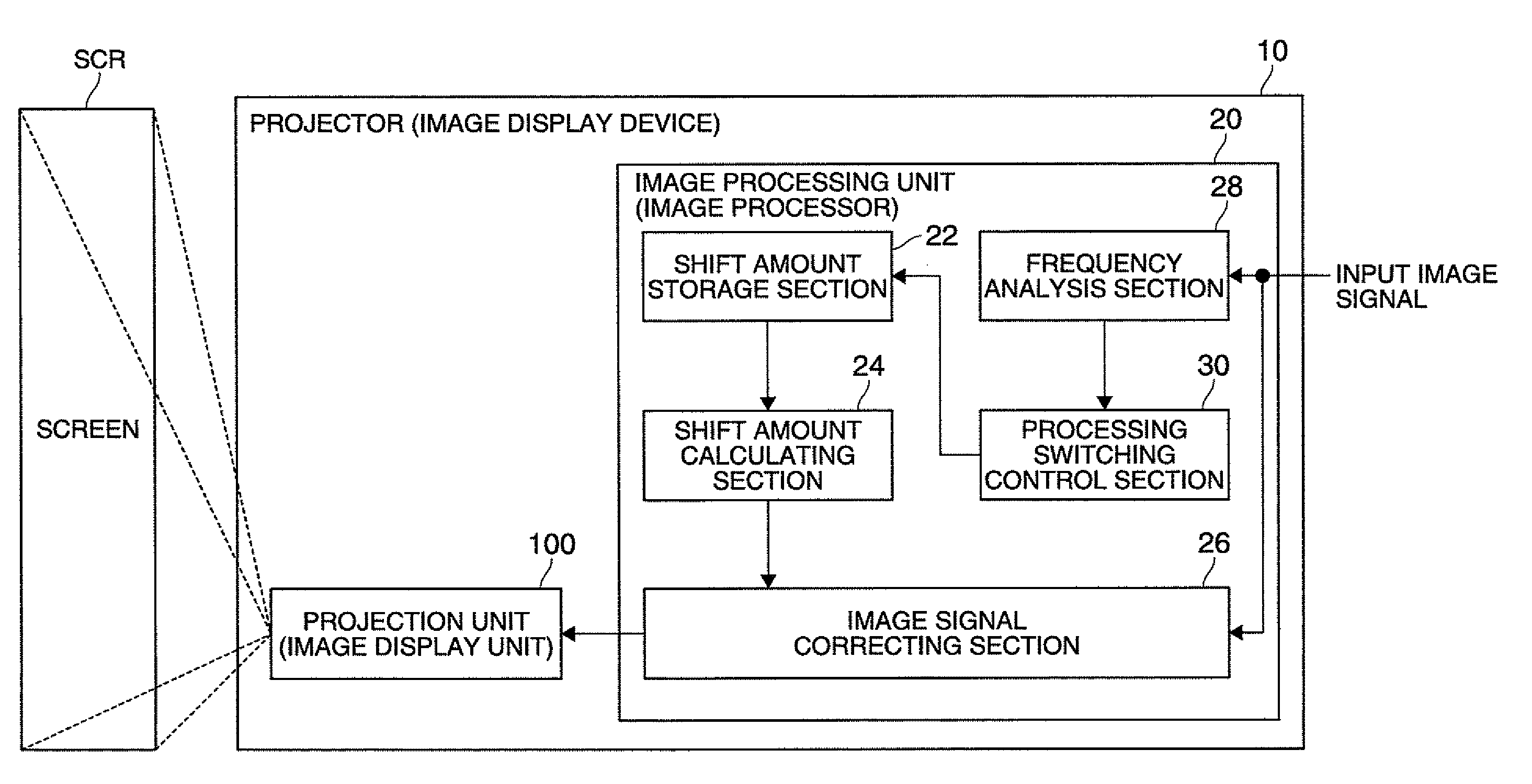
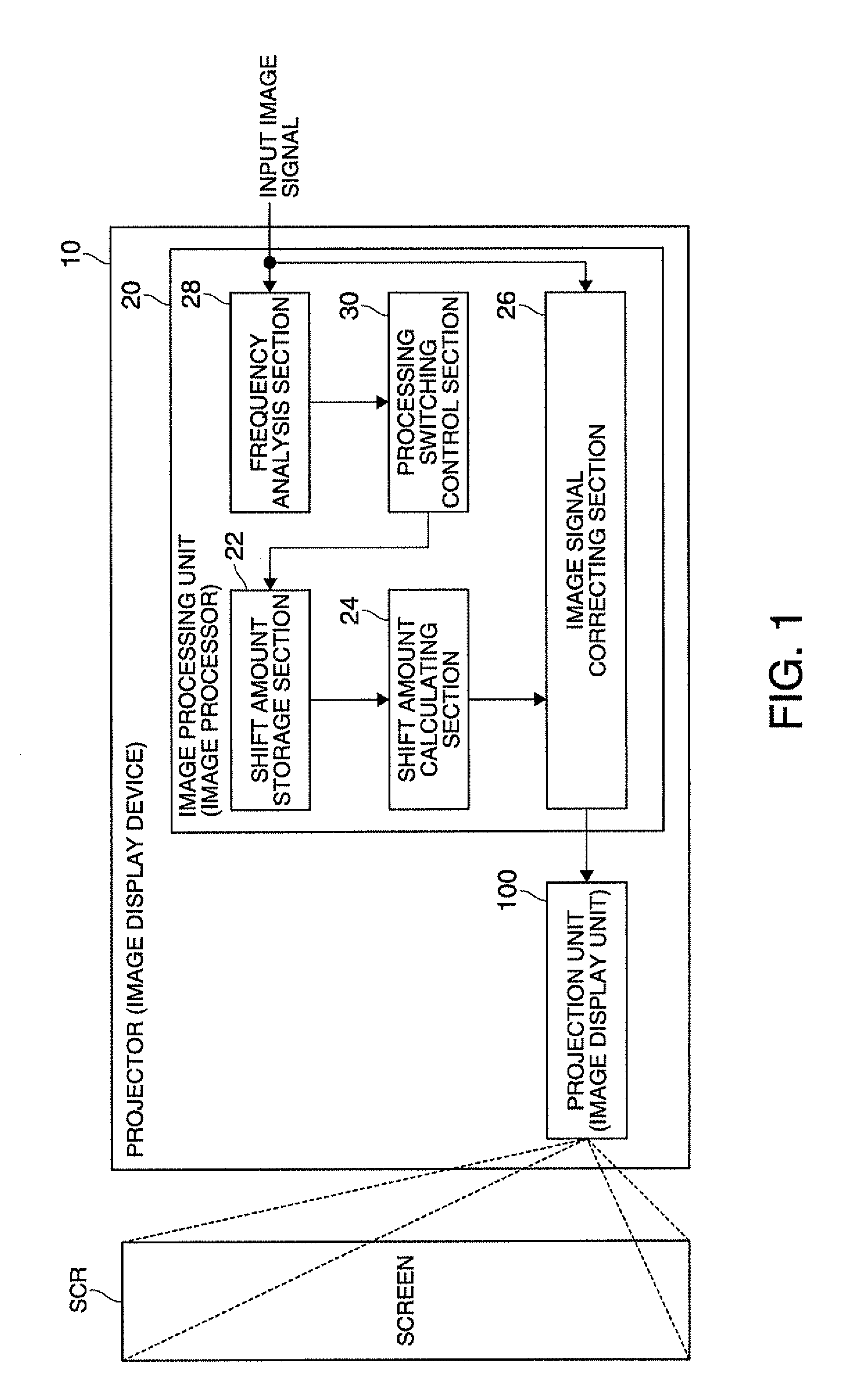
[0067]FIG. 1 is a block diagram illustrating an example of the configuration of a projector as an image display device according to a first embodiment of the invention.

[0068]A projector 10 as an image display device according to the first embodiment performs image display by projecting light, which is modulated on the basis of image signals corresponding to a plurality of sub-pixels that form one pixel, onto a screen SCR. Here, a display pixel which forms a display image projected onto the screen SCR is formed by display sub-pixels corresponding to sub-pixels that form one pixel.

[0069]The projector 10 includes an image processing unit 20 as an image processor and a projection unit 100 as an image display unit.

[0070]The image processing unit 20 performs correction processing on an input image signal, which corresponds to a pixel value of each sub-pixel, according to shift amounts of display positions of display sub-pixels which form each display pixel of the display image projected o...

second embodiment

[0158]In the first embodiment, when an input image is a high-frequency image, both x and y components of the shift amounts from the shift amount storage section 22 are set to 0 and ON / OFF control of correction processing is similarly performed on a horizontal image signal and a vertical image signal. However, the invention is not limited thereto. In a second embodiment, ON / OFF control of correction processing is individually performed on each of the horizontal image signal and the vertical image signal.

[0159]Since the configuration of a projector according to the second embodiment of the invention is the same as that of FIG. 1, illustration and detailed explanation thereof will be omitted. An image processing unit of a projector in the second embodiment is different from the image processing unit 20 in the first embodiment in configurations and operations of frequency analysis section and processing switching control section.

[0160]FIG. 16 shows an example of the configuration of mai...

third embodiment

[0192]In the first and second embodiments, when an input image is a high-frequency image, correction processing of the whole input image is controlled to be turned off. However, the invention is not limited thereto. In a third embodiment of the invention, a frequency is analyzed for each of a plurality of division images obtained by dividing an input image and different correction processing is performed on each division image according to the analysis result.

[0193]Hereinafter, an example in which an input image is divided into four parts will be described. However, the invention is not limited to the number of divided parts of the input image.

[0194]The configuration of a projector according to the third embodiment of the invention is the same as that of FIG. 1. However, in the third embodiment, a plurality of shift amounts within a display region of each of division images obtained by dividing an input image are stored in a shift amount storage section. In addition, a frequency ana...


PUM


Abstract

An image processor that corrects image signals corresponding to sub-pixels which form one pixel, includes: a shift amount storage section that stores shift amounts of display positions of display sub-pixels corresponding to the sub-pixels which form a display pixel using a predetermined reference position within a display image as a reference position; a frequency analysis section that analyzes a spatial frequency of an input image and outputs an analysis result; and an image signal correcting section that performs correction processing of image signals corresponding to the sub-pixels, which form each pixel of the input image, on the basis of the analysis result and the shift amounts, wherein the image signal correcting section performs different correction processing according to the spatial frequency.

Description

BACKGROUND[0001]1. Technical Field[0002]The present invention relates to an image processor, an image display device, an image processing method, an image display method, and a program.[0003]2. Related Art[0004]In recent years, high-performance image display devices, such as big-screen televisions or projectors, have come into wide use. In these image display devices, it is further important to improve the quality of a display image. Particularly for projectors as image display devices with high degree of freedom of installation, a demand for higher quality of a display image is becoming strong as the quality of the contents itself becomes high.[0005]As an example of such a projector, a projector in which a transmissive matrix type liquid crystal display device is used as a light valve is disclosed in JP-A-61-150487. The projector includes a plurality of dichroic mirrors, divides light from a light source into three primary colors of R, G, and B by a plurality of dichroic mirrors, a...

Claims


Application Information

Patent Timeline
Patent Type & Authority Applications(United States)
IPC IPC(8): G09G3/20
CPCG09G3/001G09G2320/0242H04N9/3185G09G2360/16G09G2340/0457
Inventor ARAGAKI, TAKUMIHASEGAWA, HIROSHI
Owner SEIKO EPSON CORP
Why Eureka
Try Eureka