Liquid crystal display apparatus

Inactive Publication Date: 2006-05-04
TOSHIBA MATSUSHITA DISPLAY TECH
View PDF2 Cites 16 Cited by
  • Summary
  • Abstract
  • Description
  • Claims
  • Application Information

AI Technical Summary

Benefits of technology

[0010] The present invention was made to solve the problems of the prior art described above. An object of the present invention is to provide a liquid crystal display apparatus, which

Problems solved by technology

In this case, the liquid crystal display apparatus may thicken and the display image may deteriorate.
However, the above method of adhering double-faced tapes to

Method used


Image

  • Liquid crystal display apparatus
  • Liquid crystal display apparatus
  • Liquid crystal display apparatus

Examples


Example

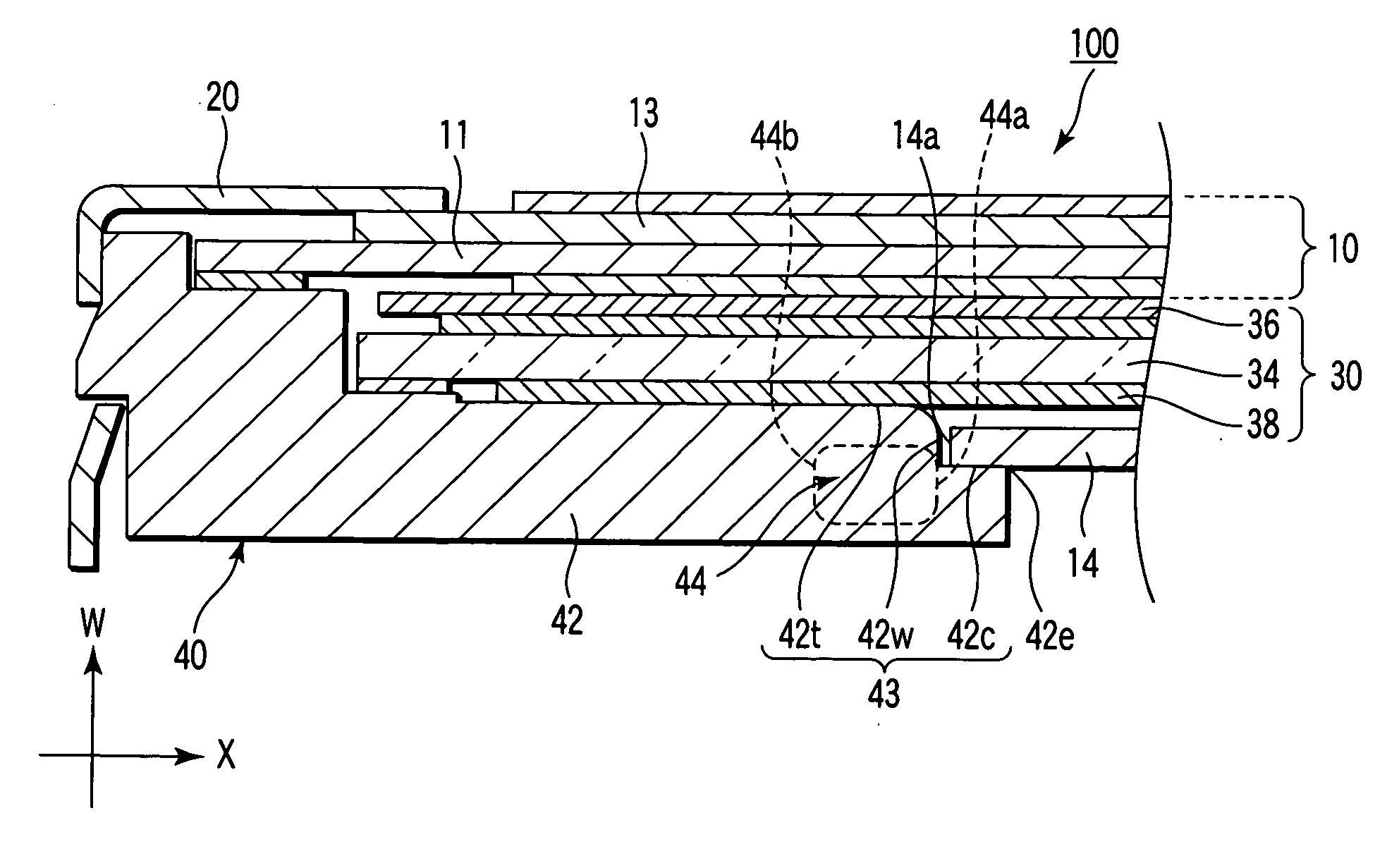
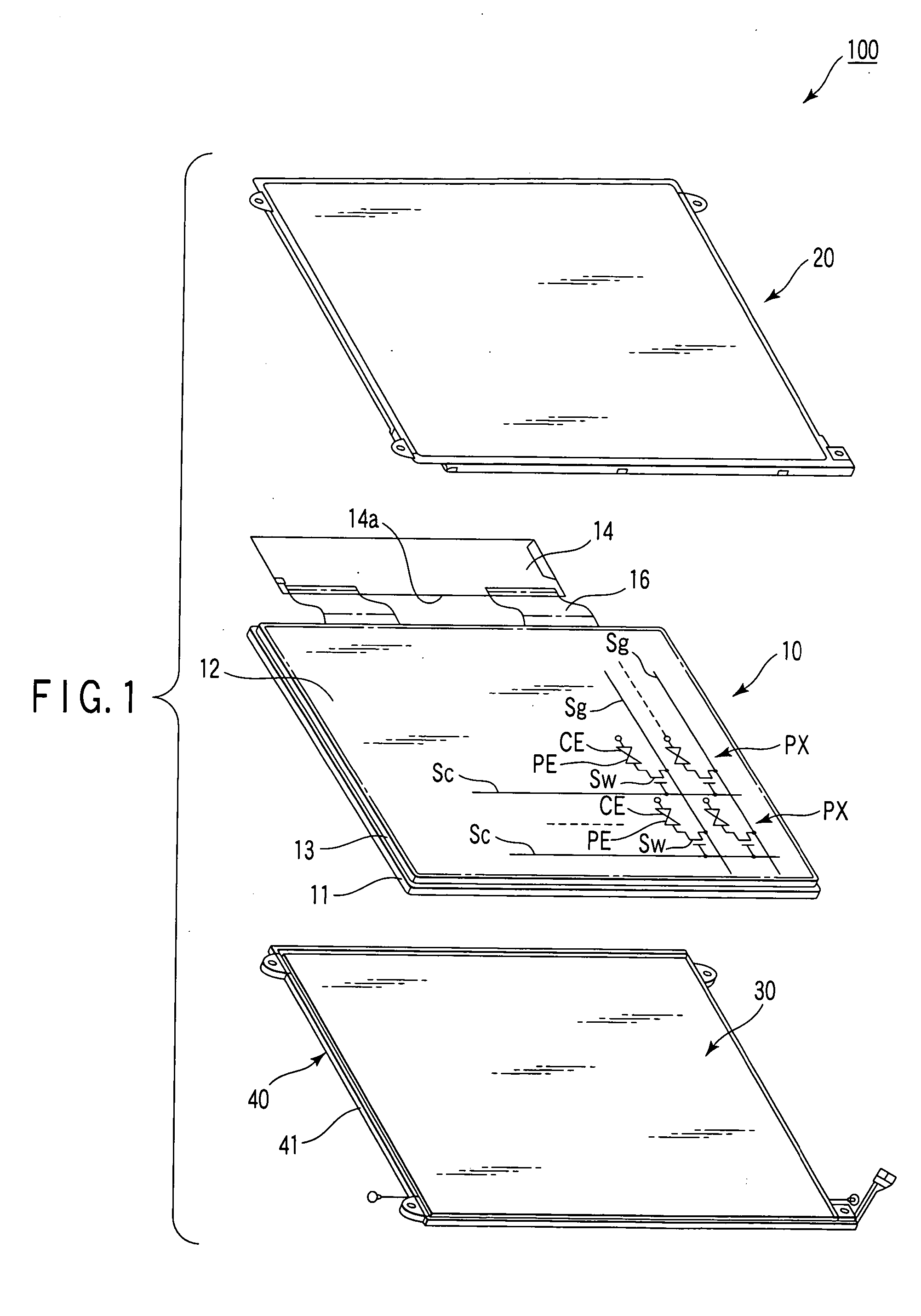
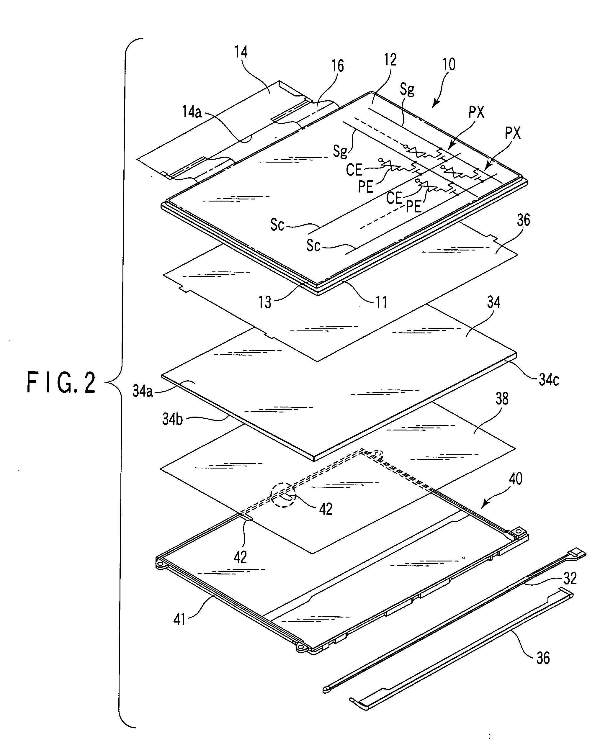
[0021] A liquid crystal display apparatus according to an embodiment of the present invention will be described with reference to the accompanying drawings. FIG. 1 is an exploded perspective view schematically showing a liquid crystal display apparatus 100 according to the embodiment. As shown in FIG. 1, the liquid crystal display apparatus 100 comprises a liquid crystal display panel 10 which is approximately rectangular; a planar light source device 30 which illuminates the liquid crystal display panel 10 from behind it; a frame 40 which supports the liquid crystal display panel 10 and the planar light source device 30; and a bezel cover 20 which is attached to the frame 40 and holds the peripheral portion of the liquid crystal display panel 10.

[0022] The liquid crystal display panel 10 comprises an array substrate 11 and a counter substrate 13, which are arranged opposite to each other. A liquid crystal layer is sandwiched between the array substrate 11 and the counter substrate...


PUM


Abstract

A liquid crystal display apparatus comprises a liquid crystal display panel including a display region in which a plurality of display pixels are arrayed, a circuit board which is electrically connected to the liquid crystal display panel, a planar light source device which illuminates the liquid crystal display panel from behind it, and a frame which supports the liquid crystal display panel and the planar light source device, and has a projection extending along a back surface of the planar light source device. The circuit board is arranged on the back surface of the planar light source device, and supported by the projection of the frame at one end thereof. The projection has a step which restrains the circuit board from moving in thickness and surface directions, and a positioning portion which allows a position where the step is formed to be visible from behind the planar light source device.

Description

CROSS-REFERENCE TO RELATED APPLICATIONS [0001] This application is based upon and claims the benefit of priority from prior Japanese Patent Application No. 2004-320893, filed Nov. 4, 2004, the entire contents of which are incorporated herein by reference. BACKGROUND OF THE INVENTION [0002] 1. Field of the Invention [0003] The present invention relates to a liquid crystal display apparatus having a frame provided with a projecting portion. [0004] 2. Description of the Related Art [0005] Generally, a liquid crystal display apparatus has a liquid crystal display panel on which a plurality of display pixels are arrayed, a circuit board which is electrically connected to the liquid crystal display panel and supplies a driving signal to the panel, a planar light source device which illuminates the liquid crystal display panel from behind it, and a frame which supports the liquid crystal display panel and the planar light source device. The frame has a projection extending along the back s...

Claims


Application Information

Patent Timeline
IPC IPC(8): G02F1/1333
CPCG02F1/133308G02F1/13452G02F2001/133314G02F1/133314
Inventor TAKEUCHI, NOBUO
Owner TOSHIBA MATSUSHITA DISPLAY TECH
Why Eureka
Try Eureka