Shield case, receptacle connector, and electronic equipment

Active Publication Date: 2011-02-10
HOSIDEN CORP
View PDF10 Cites 7 Cited by
  • Summary
  • Abstract
  • Description
  • Claims
  • Application Information

AI Technical Summary

Benefits of technology

In this aspect of the invention, the protruded portion located near the first tail portions abuts the abutting stop surface and is thereby fixed in position, so that the first and second tail portions, which are portions to be mounted on a circuit board, can be fixed with a highly accurate mounting pitch and coplanarity. In addition, it is advantageously easy to position the second contact portions of the second contacts, simply by inserting the second contact portions of the second contacts into the holes and the second long grooves of the first body.
A distance between the base and the linking portion ma

Problems solved by technology

The locking pieces are formed by cutting out portions of the bottom plate of the shield case, resulting in holes formed in the cut-out portions of the bottom plate.
A problem with the conventional connector is that solder or flux enters the shield case through the holes when solderin

Method used


Image

  • Shield case, receptacle connector, and electronic equipment
  • Shield case, receptacle connector, and electronic equipment
  • Shield case, receptacle connector, and electronic equipment

Examples


Example

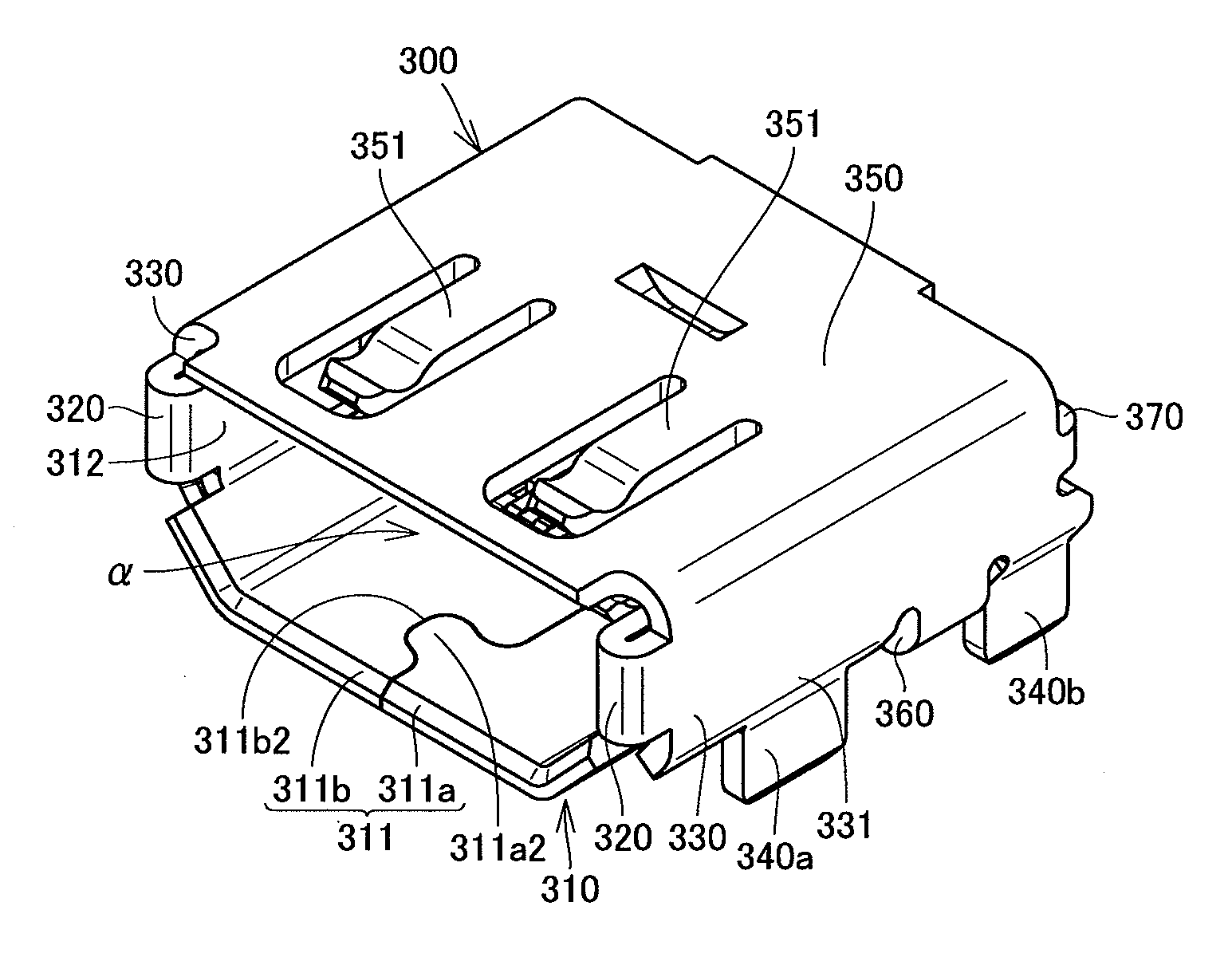
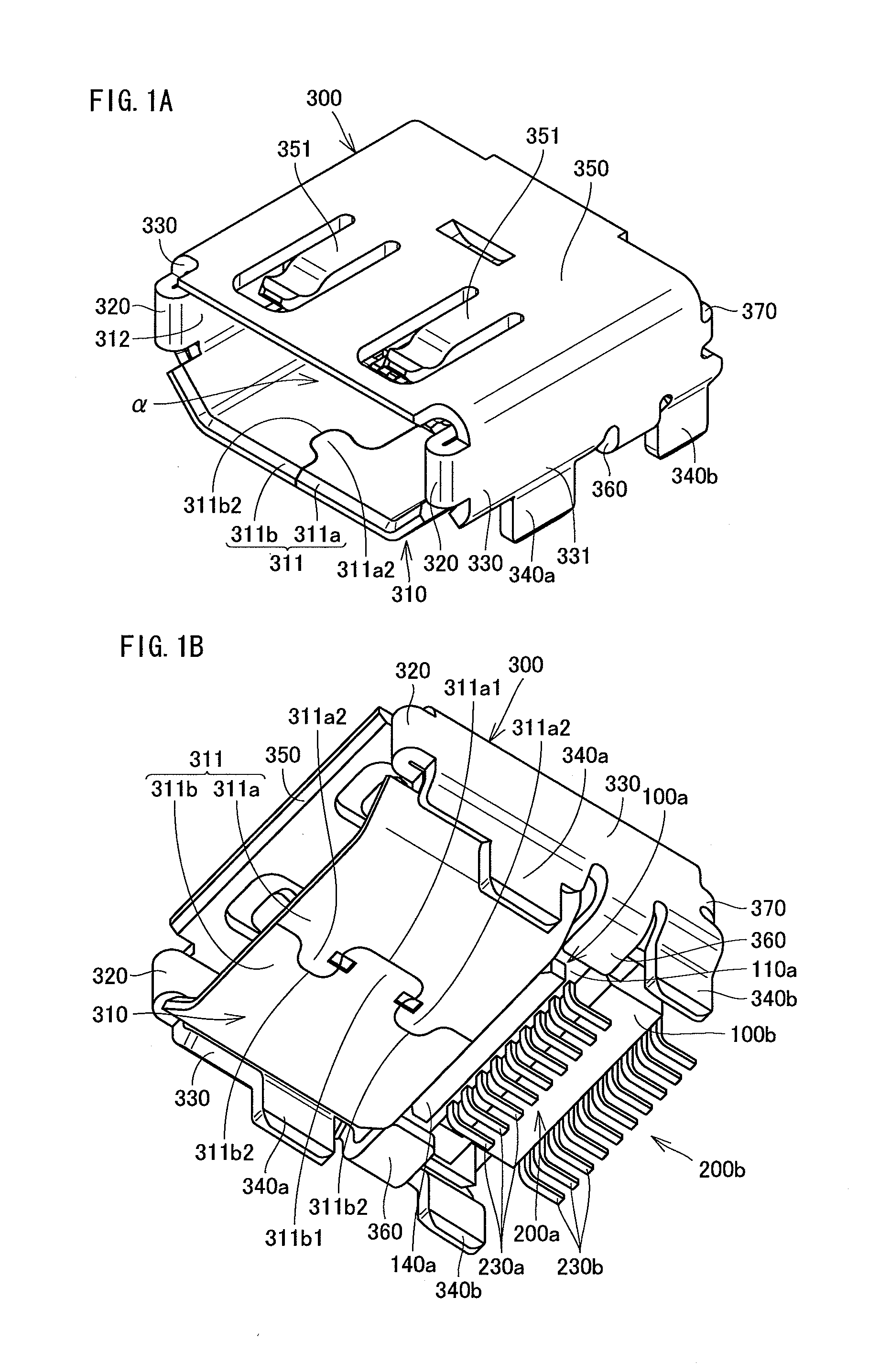
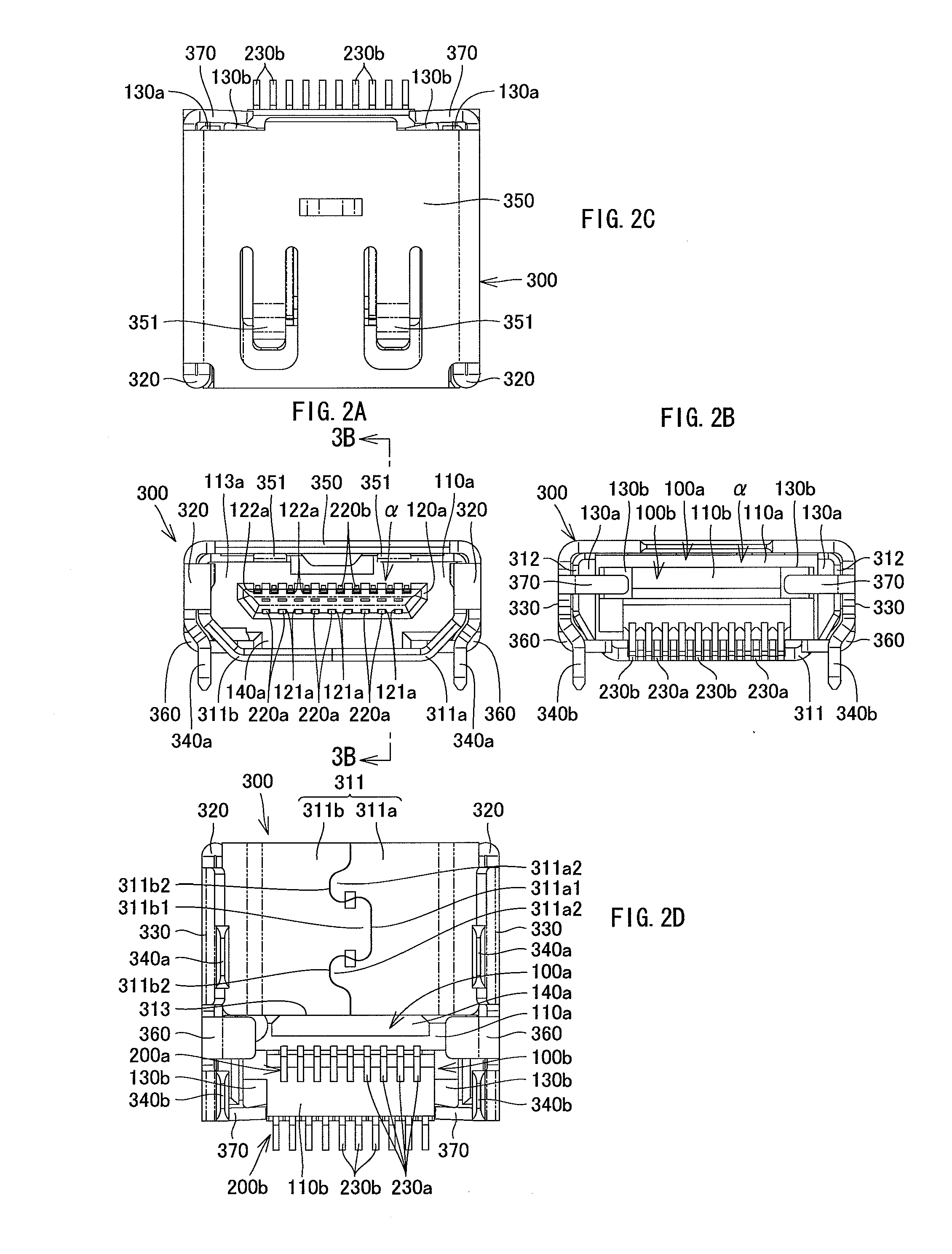
Hereinafter, a receptacle connector according to an embodiment of the present invention is described with reference to FIGS. 1A to 9. The receptacle connector shown in FIGS. 1A to 3B is compliant with the HDMI (High-Definition Multimedia Interface) standard, to be mounted on a circuit board 10 of an electronic equipment, such as a television receiver, and used as an external interface of the electronic equipment. The receptacle connector includes first and second bodies 100a, 100b, a plurality of first and second contacts 200a, 200b, and a shield case 300. The respective elements of the connector will be described in detail below.

The first body 100a is a molded article of insulating resin, as shown in FIGS. 1B to 6B. The first body 100a has a main body 110a, a projected portion 120a, a pair of walls 130a, and an elongated protrusion 140a (protruded portion). The main body 110a is a plate-like body having a generally rectangular shape in cross-sectional view. A plurality of generally...


PUM


Abstract

A shield case of the invention includes a base of a generally U-shape in front view having widthwise end portions, the end portions each having a front surface and a back surface; a pair of folded-back portions, provided on the front the back surfaces of the end portions of the base and folded back backward, or alternatively provided on the back surfaces of the end portions of the base and folded back forward; a pair of side walls, extending from the folded-back portions along a length of the end portions of the base; a pair of first locking pieces, extending downward from the side walls; and a linking portion adapted to link between the side walls. The base, the side walls, and the linking portion define a body containing portion.

Description

The present application claims priority under 35 U.S.C. §119 of Japanese Patent Application No. 2009-185114 filed on Aug. 7, 2009, the disclosure of which is expressly incorporated by reference herein in its entity.BACKGROUND OF THE INVENTION1. Technical FieldThe present invention relates to a shield case to be mounted on a circuit board, a receptacle connector including the shield case, and an electronic equipment including the receptacle connector.2. Background ArtA conventional receptacle connector of this type has a shield case as disclosed in paragraph 0024 and FIGS. 1 and 4 of Patent Literature 1 for the purpose of reducing the mounting height. More particularly, a bottom plate of the shield case having a generally O shape in front view is directly placed on a circuit board and is fixed onto the circuit board by engaging locking pieces of the shield case with locking holes of the circuit board. The locking pieces are formed by cutting out portions of the bottom plate of the sh...

Claims


Application Information

Patent Timeline
IPC IPC(8): H01R13/648H05K9/00
CPCH01R13/506H01R23/6873H01R12/712H01R13/6594H01R13/6582H01R13/64H01R13/641H01R13/648H01R13/6485H01R13/658H01R13/6581H01R13/6583
Inventor NAGATA, TAKAYUKIASANO, TAKAO
Owner HOSIDEN CORP
Why Eureka
Try Eureka