Connector with lock mechanism

Inactive Publication Date: 2005-08-18
JST MFG CO LTD
View PDF11 Cites 8 Cited by
  • Summary
  • Abstract
  • Description
  • Claims
  • Application Information

AI Technical Summary

Benefits of technology

[0035] In order to solve the problems described above, it is an object of the present invention to provide a connector with a lock mechanism having a lock arm, the lock mechanism being constructed

Problems solved by technology

That is, a change of design such as an increase

Method used


Image

  • Connector with lock mechanism
  • Connector with lock mechanism
  • Connector with lock mechanism

Examples


Example

[0088] The preferred embodiment of the present invention will be described below in reference to the drawings. However, the present invention is not limited to the embodiment, and various modifications and changes in design can be made without departing from the scope of the invention.

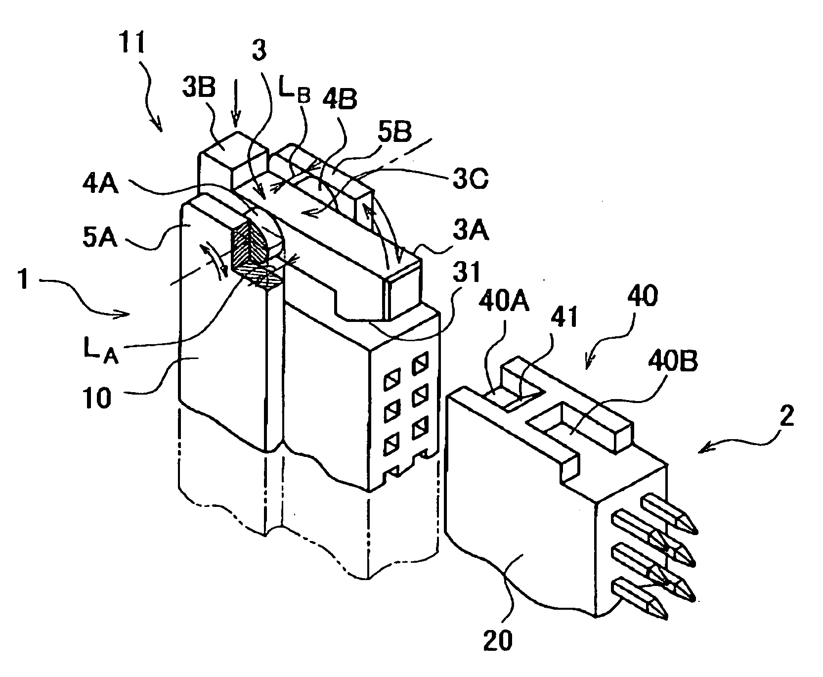
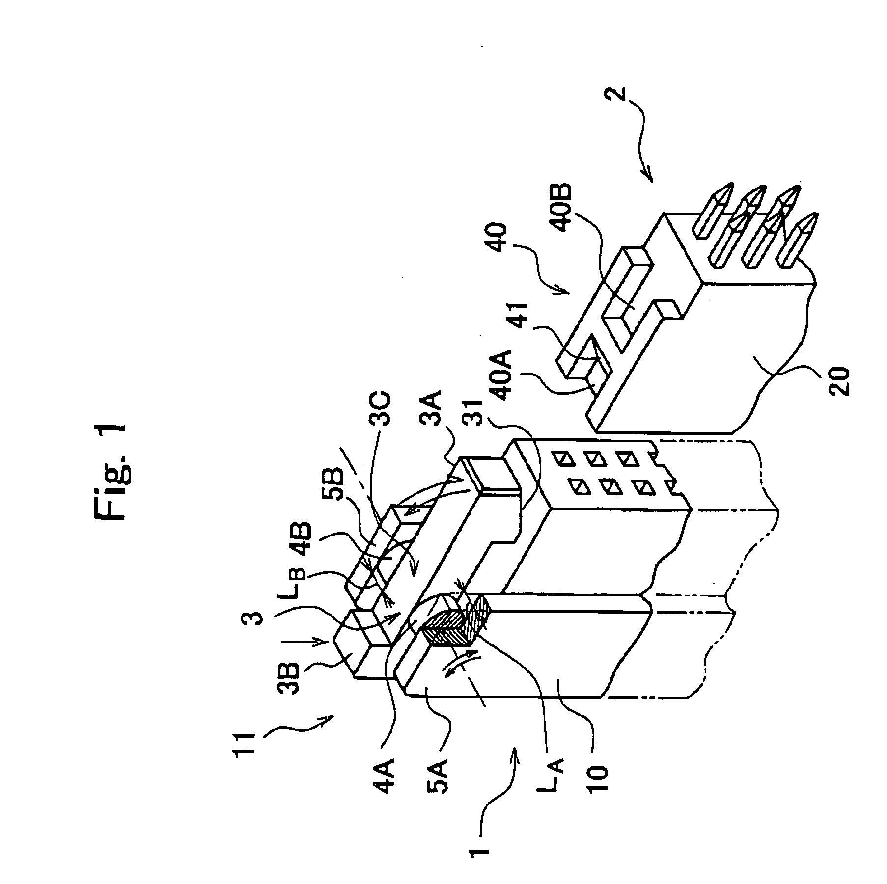
[0089]FIG. 1 is a perspective view showing a part of a connector with a lock mechanism according to an embodiment of the present invention. FIG. 1 depicts only main parts. In FIG. 1, the reference numeral 1 denotes a plug to perform as a connector of the present invention, 2 denotes a receptacle to perform as a mating connector, and 11 denote a lock mechanism.

[0090] In the embodiment shown in FIG. 1, the plug 1 comprises a shell-type multipolar, rectangular connector. A plug housing 10 has an outer shell molded from an insulating synthetic resin to be rectangular in shape. The plug housing 10 is connected thereto a plurality of “female” contacts with cables.

[0091] On the other hand, in the embodimen...


PUM


Abstract

A connector with a lock mechanism, in which maximum stress generated at a hinge joint as a fulcrum portion of a lock arm is reduced. A lock arm 3 is provided on an outer wall of a plug housing 10. A plug 1 comprises a lock mechanism 11, in which the lock arm 3 is latched on a latch 40 provided on a receptacle 2 for maintaining a state of coupling to the receptacle 2. The lock arm 3 comprises a hook 3A projecting in a direction of insertion of the receptacle 2, a point of pressure 3B (a finger depressing portion) positioned on an opposite side to the hook 3A, and a fulcrum portion 3C. The fulcrum portion 3C has a pair of torque rods 4A, 4B supporting the lock arm 3 at lateral ends so as to allow the hook 3A to swing.

Description

CROSS-REFERENCE TO RELATED APPLICATIONS [0001] This application is based upon and claims the benefits of priorities from Japanese Patent Application No. 2004-012248 filed on Jan. 20, 2004, the entire contents of which are incorporated herein by reference. [0002] This application is related to a co-pending U.S. patent application entitled “Lock Structure and Connector with Lock Mechanism of Lock Structure,” and being filed on even date herewith. The co-pending application is expressly incorporated herein by reference. FIELD OF THE INVENTION [0003] The present invention relates to a connector for electric connection, having a lock mechanism capable of mechanically holding on to a mating connector. RELATED ART [0004] A set of connectors for electric connection are constructed such that a connector, on which a socket contact with a plurality of cables is mounted, and a connector with a plurality of pin contacts are coupled to each other. In this case, a receptacle is mounted to an elect...

Claims


Application Information

Patent Timeline
IPC IPC(8): H01R13/639G06K17/00H01R13/627H01R13/629
CPCH01R13/6273A41D1/06A41F9/00
Inventor SHIMIZU, KAZUOMIONCHI, AKIHIKOMIYACHI, DAISUKE
Owner JST MFG CO LTD
Why Eureka
Try Eureka