

Horn switch device, airbag system, and steering wheel
- Summary
- Abstract
- Description
- Claims
- Application Information
AI Technical Summary
Benefits of technology
Problems solved by technology
Method used
Image

Examples
first embodiment
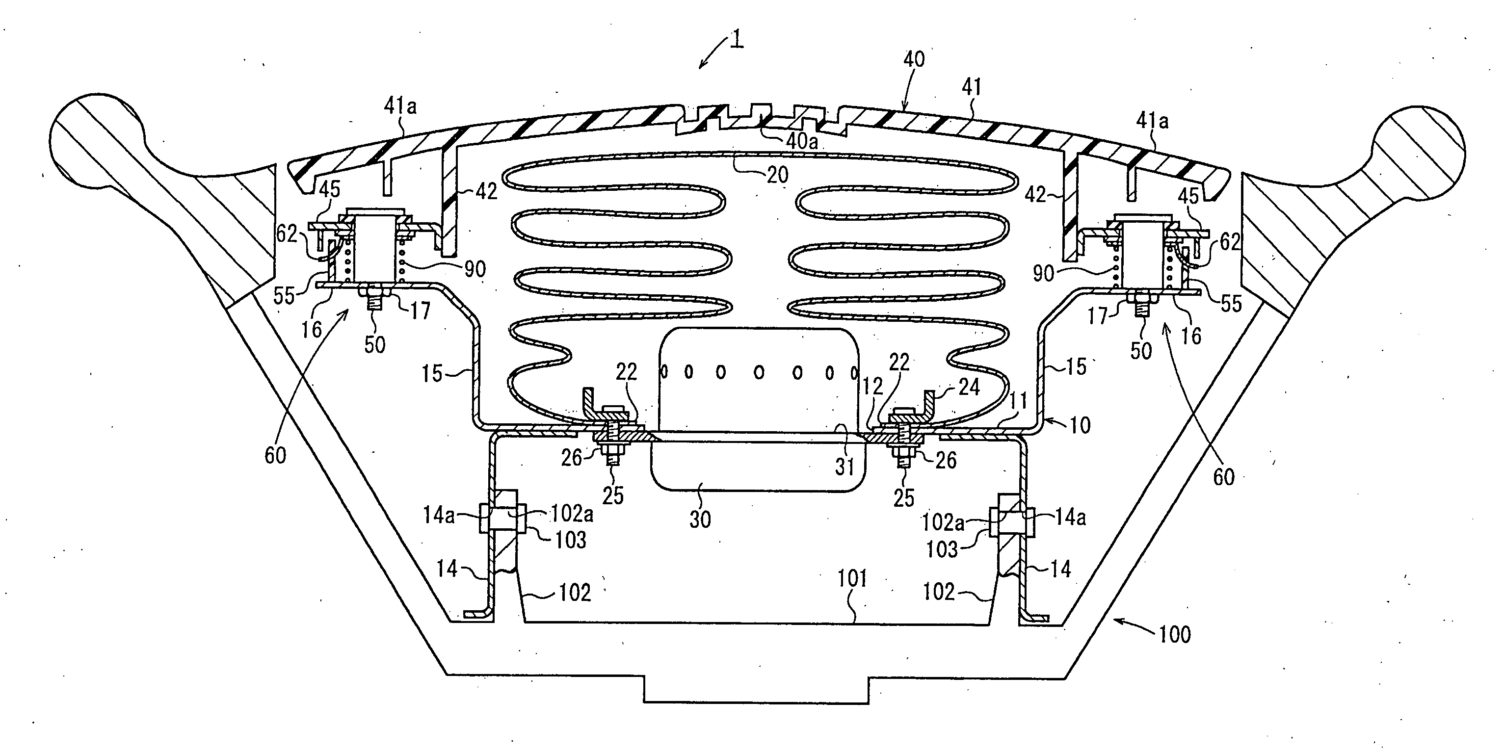
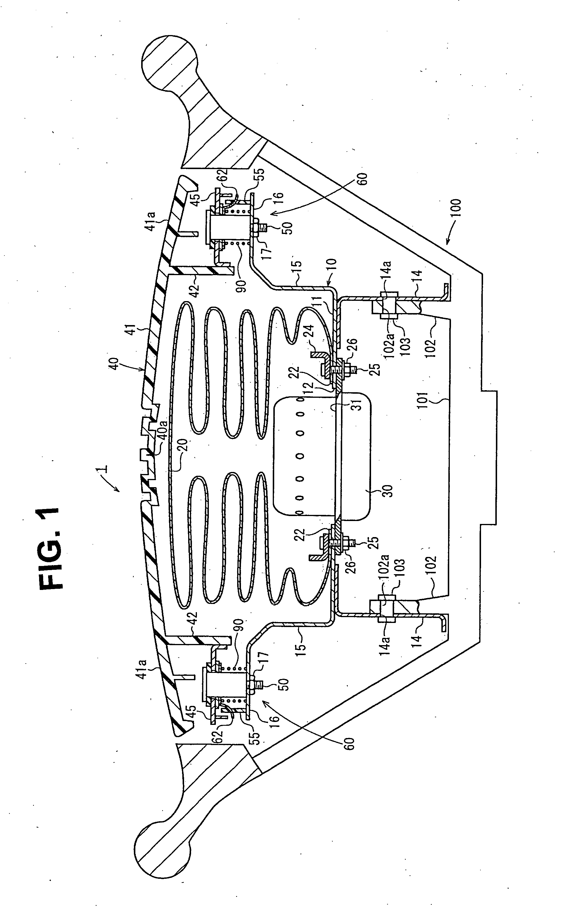
[0023]FIG. 1 is a cross-sectional view of a steering wheel equipped with an airbag system including a horn switch device according to the present invention.
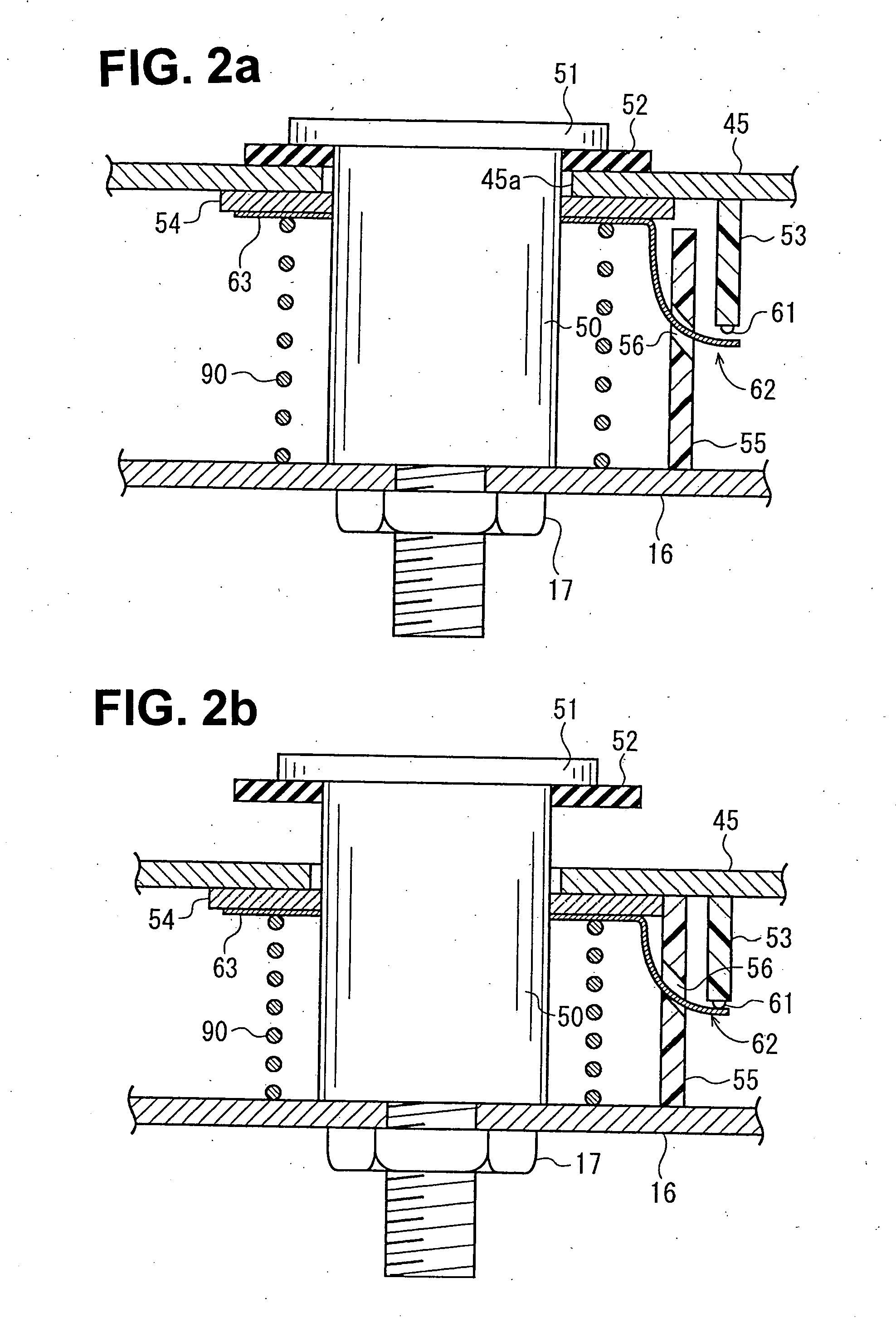
[0024] FIGS. 2(a) and 2(b) are enlarged views of the horn switch device depicted in FIG. 1. FIG. 2(a) shows “an undepressed” state in which a module cover 40 is not depressed, and FIG. 2(b) shows “a module-cover depressed state” in which the module cover 40 is depressed to sound a horn.
[0025] The airbag system 1 is a driver-seat airbag system disposed in the center (a base 101) of a steering wheel 100. The airbag system 1 includes a metal retainer 10, an airbag 20 mounted to the retainer 10 with an airbag-fixing ring 24, an inflator 30 for inflating the airbag 20, a synthetic-resin module cover 40 that covers the folded airbag 20, and a horn switch device 60.
[0026] According to the first embodiment of the invention, the module cover 40 is a retractable body. The module cover 40 has a groove-like tear line 40a. When the airbag 2...
second embodiment
[0049] The airbag system 1A also includes a retainer 10A, an airbag 20 mounted to the retainer 10A with a ring 24, an inflator 30 for inflating the airbag 20, a module cover 40A that covers the folded airbag 20, and a horn switch device 60. According to this second embodiment of the invention, the entire airbag system 1A is a retractable body.
[0050] The retainer 10A of this embodiment also has a substantially rectangular main plate 11. The airbag 20 and the inflator 30 are mounted to the main plate 11, whose mounting structure is the same as that of the airbag system 1 depicted in FIG. 1.
[0051] An enclosure 15A extends upward (i.e., in FIG. 3, toward the occupant) from the outer rim of the main plate 11 of the retainer 10A. An extension 16A extends laterally (i.e., to the side of the airbag system 1A or in the direction perpendicular to the direction in which the airbag system 1A retracts (vertically in FIG. 3)), from the distal end of the enclosure 15A in the standing direction.
[...
PUM
 Abstract
Description
Claims
Application Information