Fastener

a technology of fasteners and fasteners, applied in the field of fasteners, can solve the problems of poor workability and an additional burden on the operator, and achieve the effect of improving workability

Inactive Publication Date: 2005-05-24
NIFCO INC
View PDF12 Cites 64 Cited by
  • Summary
  • Abstract
  • Description
  • Claims
  • Application Information

AI Technical Summary

Benefits of technology

[0012]When the female member in this temporarily assembled condition is inserted into the mounting holes of the plate members, the projecting portion formed on the outer peripheral surface of the cylinder body abuts against one of the plate members. Thus, the position of the female member in the inserting direction is set. When the male member is further inserted into the female member, an insertion load is created due to an engagement of the second male screw with the engaging portion. This load is maintained until the second male screw is disengaged from the engaging portion. When the second male screw is disengaged from the engaging portion, the insertion load is released. From this point, the male member again can be easily inserted into the female member until the first male screw reaches the engaging portion. When the first male screw reaches the engaging portion, the insertion load is created again.
[0014]Accordingly, when the male member is inserted into the female member in the operation of fixing the plate members, since there is a period when an insertion load is released, the workability is improved, and burden to an operator is reduced.
[0019]As described above, even in the structure in which the engaging portion is formed on the outer peripheral surface of the main body of the male member and the two female screws disposed at a predetermined interval are formed on the cylinder of the female member, the insertion load can be released when inserting the male member into the female member, resulting in an improvement in workability.

Problems solved by technology

This continuous insertion load causes poor workability and an additional burden to an operator.

Method used


Image

  • Fastener
  • Fastener
  • Fastener

Examples


Embodiment Construction

[0033]Hereunder, embodiments of the invention will be explained with reference to the accompanied drawings.

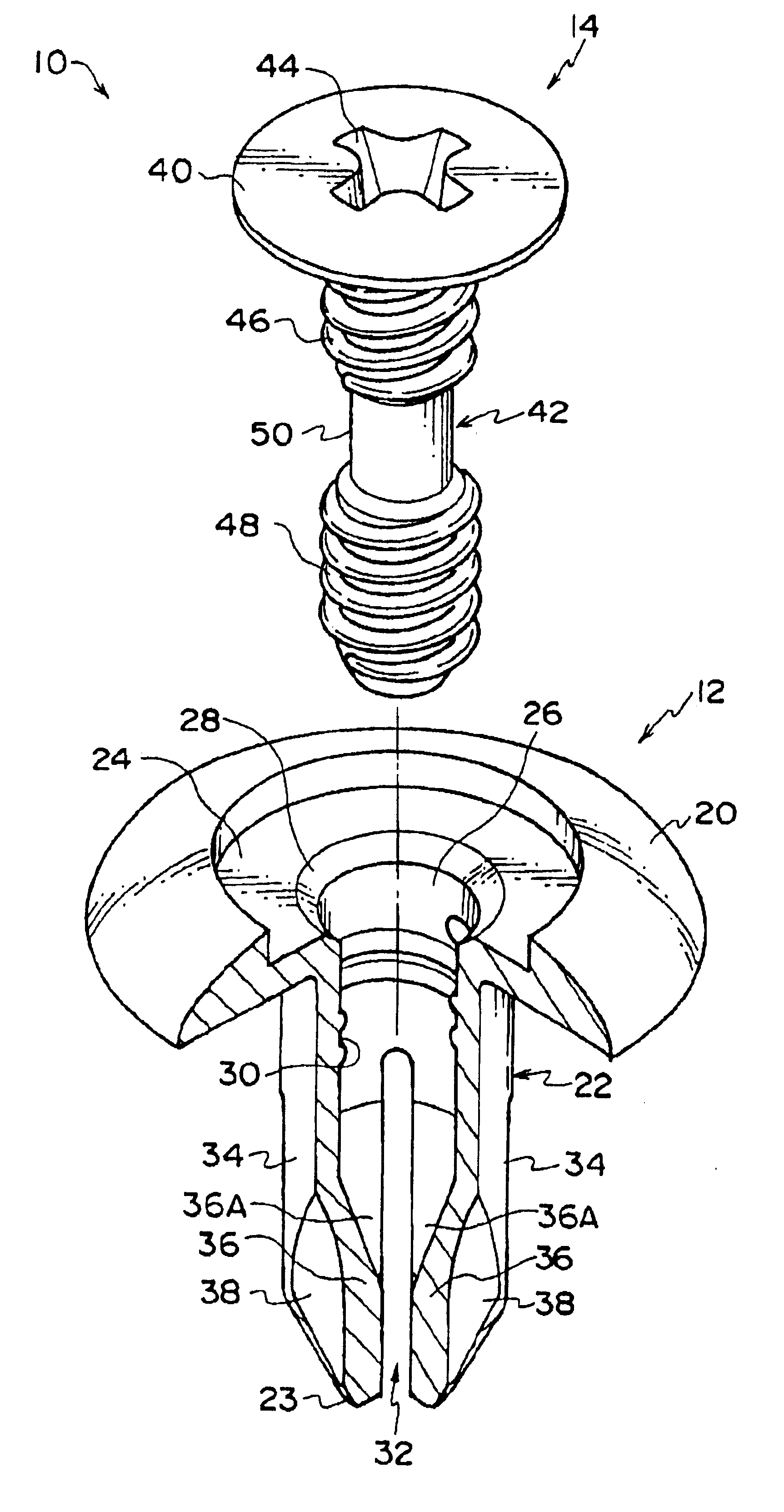
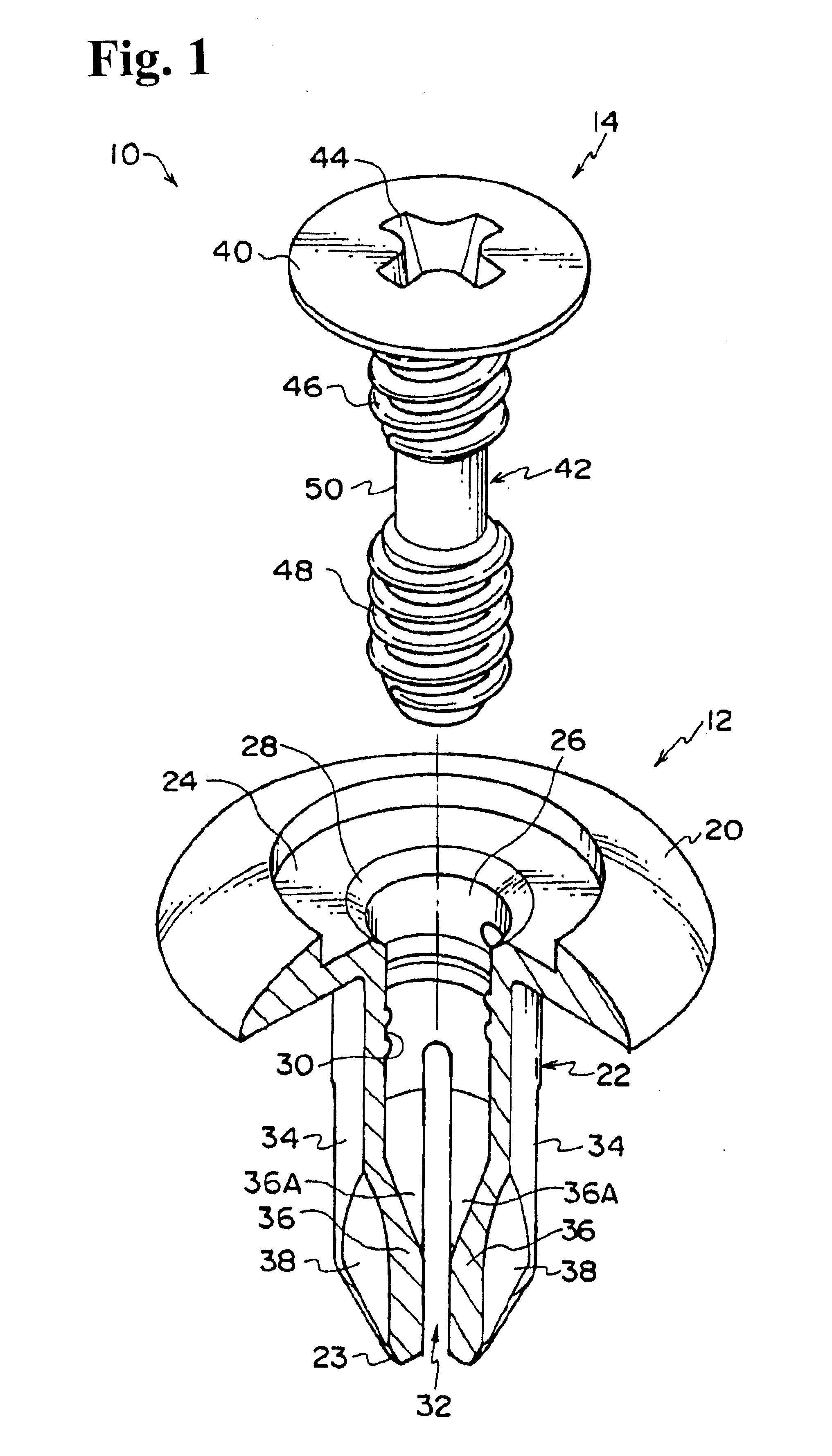
[0034]FIG. 1 shows an exploded perspective view of a fastener (fastening device) according to an embodiment of the invention, and a fastener 10 is formed of a grommet 12 and a pin 14, which are formed by a flexible resin. FIG. 2 to FIG. 5(B) shows the grommet 12, and FIG. 6 to FIG. 8(B) shows the pin 14.

[0035]Firstly, the grommet 12 will be explained. The grommet 12 includes a cylinder body 22 that is provided with a circular flange 20 at an upper end portion of an outer peripheral surface thereof. The flange 20 has a substantially tapered shape, in which an end portion side of an upper surface is gently sloped downwardly, and a circular concave portion 24 having a diameter larger than that of the cylinder body 22 is formed at a center of the upper surface of the flange 20.

[0036]The cylinder body 22 has a tapered shape in which a diameter of an outer peripheral surface of a dis...


PUM


Abstract

A fastener for connecting plate members includes a male member, and a female member to be inserted into mounting holes of the plate members. The female member includes a cylinder body for receiving the main body therein, a projecting portion formed on an outer periphery of the cylinder body at one end thereof, and protruding portions formed at the other end thereof. A first engaging portion is formed on an outer surface of a main body of the male member or an inner surface of the cylinder body, and a second engaging portion engaging the first engaging portion is formed on the inner surface or the outer surface. The second engaging portion has two engaging sections and a smooth surface portion interposed therebetween. When the male member is inserted into the female member, the male member can be easily engaged with the female member.

Description

BACKGROUND OF THE INVENTION AND RELATED ART STATEMENT[0001]The present invention relates to a fastener for fixing laminated plate members.[0002]A conventional fastener for fixing laminated plate members is shown in FIG. 12 and FIG. 13, which is disclosed in Japanese Utility Model Publication (KOKOKU) No. S58-60016.[0003]A fastener 100 comprises a grommet 102 and a pin 104, which are formed of a flexible resin. The grommet 102 is inserted into mounting holes 110 and 112 of plate members 106 and 108, which are positioned and laminated, and the pin 104 is inserted into the grommet 102, so that the plate members 106 and 108 are fixed so as not to be separated from each other.[0004]The grommet 102 includes a cylinder member 122 provided with a flange 120, and when the cylinder member 122 is inserted into the mounting holes 110 and 112, the flange 120 abuts against the upper plate member 106 to regulate the position of the grommet 102 in an inserting direction. On an inner peripheral surf...

Claims


Application Information

Patent Timeline
Patent Type & Authority Patents(United States)
IPC IPC(8): F16B19/04F16B19/10F16B13/04
CPCF16B19/1081
Inventor ENOMOTO, RYOTASHIMA, TAKUOZEKI, TADASHI
Owner NIFCO INC
Why Eureka
Try Eureka