
Airbag

a technology for airbags and occupants, applied in the field of airbags, can solve the problems of increasing labor and affecting productivity

Inactive Publication Date: 2005-05-03
JOYSON SAFETY SYST JAPAN KK
View PDF22 Cites 68 Cited by
  • Summary
  • Abstract
  • Description
  • Claims
  • Application Information

AI Technical Summary

Benefits of technology

[0007]An object of the present invention is to provide an airbag where gas is prevented from leaking at seams between panels and which has excellent productivity.
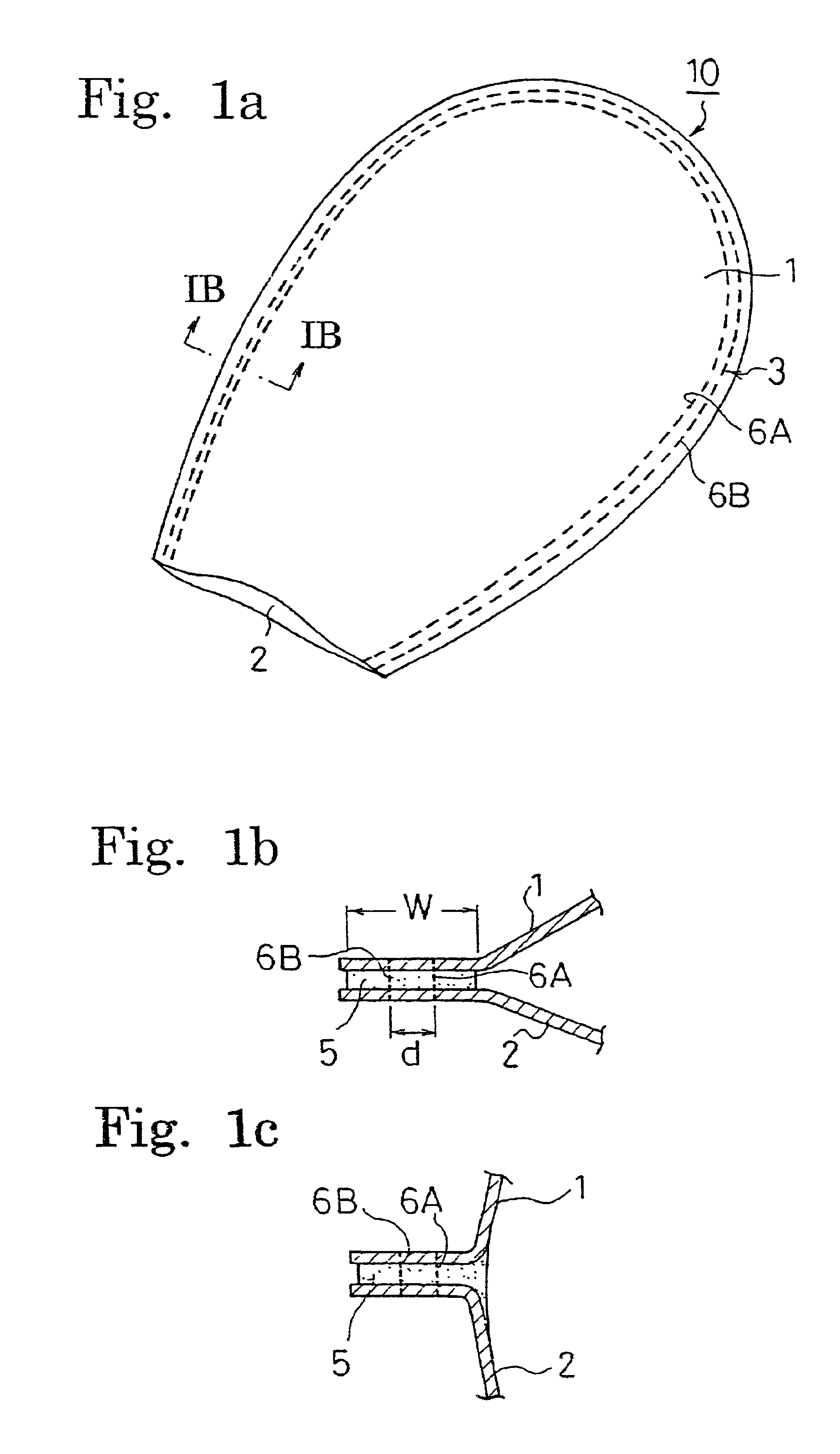
[0011]The airbag of the present invention has little or no gas leakage, since the first panel and the second panel are not only sewn together but also bonded by the elastic adhesive along their peripheries. When the panels are sewn together after bonding the panels with the elastic adhesive, the panels are prevented from slipping to each other during the sewing operation, thus improving the sewing workability. The sewing yarns seaming the panels through the elastic adhesive are prevented by the elastic adhesive from coming into contact directly with gases from the inflator.
[0012]The seams may include a first seam positioned outside and a second seam positioned inside, and sewing yarn for the second seam may be thinner than sewing yarn for the first seam. The sewing yarn for the second seam positioned inside is broken during the inflation of the airbag so as to partially absorb energy of gas pressure. This energy absorption reduces the impact applied to the sewing yarn for the first seam positioned outside during the inflation of the airbag.
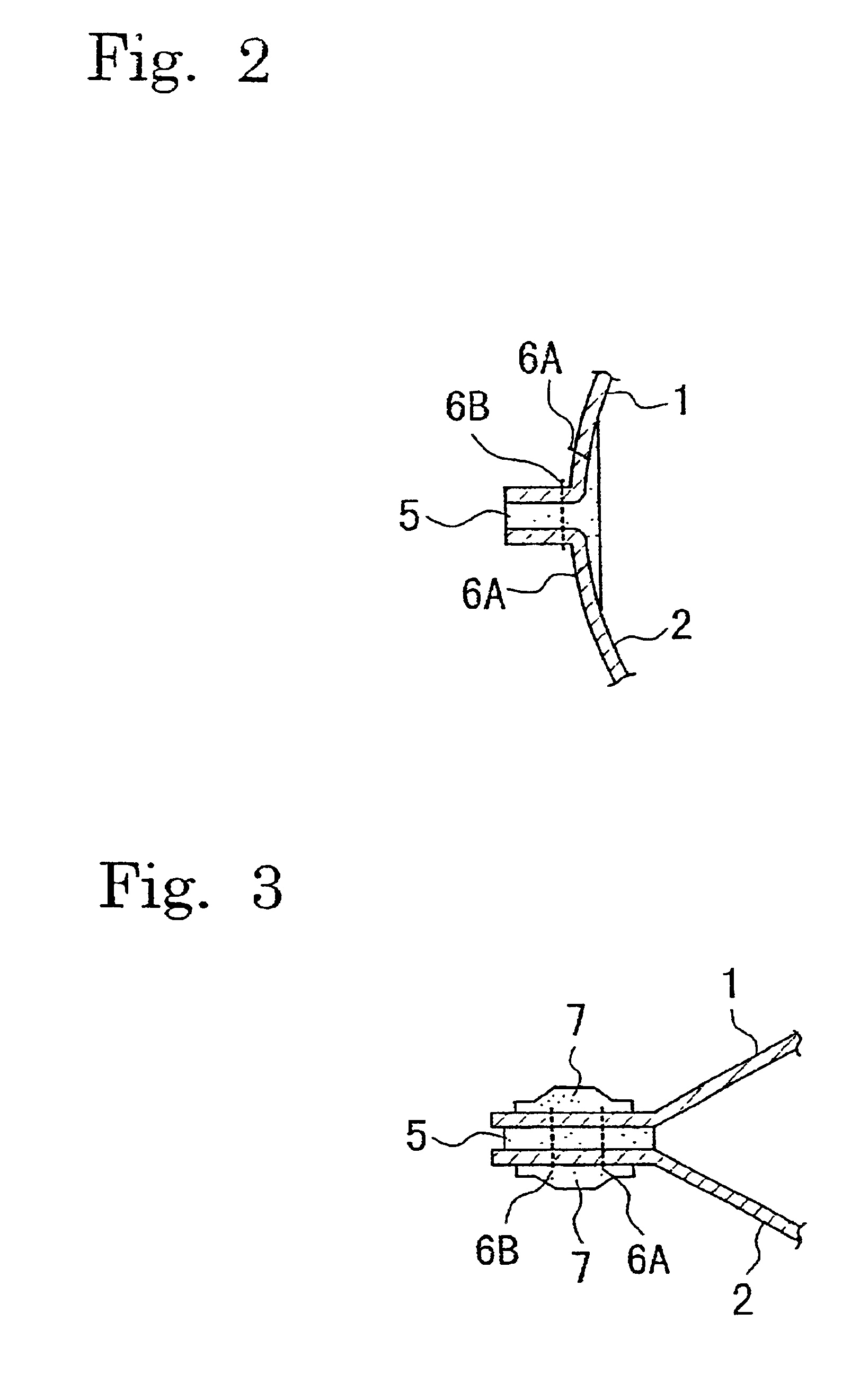
[0013]The seam of the panels may be covered by elastic sealant, thereby preventing the gas leakage at the stitches. The sealant is preferably silicone or urethane sealant. If the panel is coated with silicone coating, the sealant is preferably silicone sealant. If the panel is coated with urethane coating, the sealant is preferably urethane sealant.
[0016]The elastic adhesive is preferable to be as flexible as possible so that the airbag becomes easy to be folded with a small bending resistance of the airbag whereby reducing a packaging volume of the airbag.
[0018]The elastic adhesive may be partially applied to the airbag, and each portion of the elastic adhesive may have a configuration like a column. The column of the elastic adhesive prevents air from remaining in the hardened elastic adhesive which bonds the panels.

Problems solved by technology

In the conventional air bag in FIGS. 4a, 4b, the silicone tapes 4 must be attached to the both surfaces of the airbag, thereby increasing the labor and impairing the productivity.

Method used


Image

  • Airbag
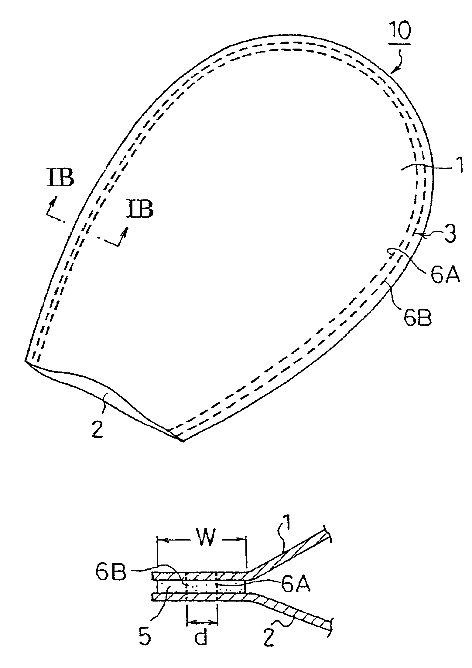
  • Airbag
  • Airbag

Examples


Embodiment Construction

[0026]Hereinafter, embodiments of the present invention will be described with reference to the attached drawings.

[0027]FIG. 1a is a perspective view showing an embodiment of an airbag according to the present invention, FIG. 1b is an enlarged sectional view taken along a line IB—IB of FIG. 1a, FIG. 1c is a sectional view of the same part shown in FIG. 1b when the airbag is inflated and deployed.

[0028]Though an airbag 10 shown in FIGS. 1a-1c is a side airbag for an automobile, it should be understood that the present invention is not limited thereto and may be applied to automobile airbags for a driver's seat, a front passenger's seat, and a rear passenger's seat and also to an airbag for an aircraft.

[0029]The airbag 10 has a first panel 1 and a second panel 2 which are sewn together along peripheries thereof. The peripheries of the first and second panels 1, 2 are bonded by elastic adhesive 5 such as silicone or urethane adhesive and sewn together by sewing yarns 6A, 6B. During the...


PUM


Abstract

An airbag is provided which securely prevents gas leakage through seams between panels and has excellent productivity. The airbag 10 has panels 1, 2. Peripheral portions of the panels 1, 2 are bonded with silicone adhesive 5 and also sewn together by sewing yarns 6A, 6B. Seams of the sewing yarns 6A, 6B may be coated by silicone sealant. The sewing yarn 6A composing an inner seam is thinner than the sewing yarn 6B composing an outer seam so that the sewing yarn 6A is broken during the inflation of the airbag 10, thereby absorbing energy.

Description

CROSS REFERENCE TO RELATED APPLICATION[0001]This is a continuation-in-part application of patent application Ser. No. 09 / 318,251 filed on May 25, 1999, abandoned, and Ser. No. 09 / 342,171 filed on Jun. 29, 1999, abandoned.BACKGROUND OF THE INVENTION AND RELATED ART STATEMENT[0002]The present invention relates to an airbag for an airbag device installed in a vehicle and an aircraft and, more particularly, to an airbag where gas is prevented from leaking from seams between panels.[0003]A vehicle airbag for an automobile, such as a driver's airbag, a front passenger's airbag, a rear passenger's airbag, and a side airbag, or an airbag for an aircraft, has a plurality of panels which are sewn together in a bag-like configuration. The airbag is inflated by gas supplied from an inflator.[0004]An airbag which requires to retain its internal pressure for a long time is desired to extremely prevent gas leakage through seams. Such an airbag is for example a side airbag (of a curtain type) for p...

Claims


Application Information

Patent Timeline
Patent Type & Authority Patents(United States)
IPC IPC(8): B60R21/16B60R21/233B60R21/235
CPCB60R21/2342B60R21/235B60R21/232B60R2021/23595B60R2021/23576B60R2021/2358B60R2021/23316
Inventor MISHINA, JYOJIMASUDA, YASUSHINAKANISHI, RYOSUKE
Owner JOYSON SAFETY SYST JAPAN KK
Learn More