Power assist apparatus with a controlled brake mechanism for positioning a workpiece and control method thereof

a technology of brake mechanism and workpiece, which is applied in the direction of programme control, hoisting equipment, instruments, etc., can solve the problems of reducing the efficiency of conveyance, affecting the operation of the arm or each joint, and affecting the efficiency of the conveyance, so as to prevent the breakage of the workpiece, improve efficiency, and stabilize the effect of the conveyan

Inactive Publication Date: 2012-07-24
TOYOTA JIDOSHA KK
View PDF27 Cites 47 Cited by
  • Summary
  • Abstract
  • Description
  • Claims
  • Application Information

AI Technical Summary

Benefits of technology

[0011]To prevent breakage of a workpiece while the workpiece is conveyed by a power assist apparatus and improve efficiency with which a workpiece is conveyed by the power assist apparatus, the present invention provides a power assist apparatus and a control method thereof with which the attitude of the workpiece can be stabilized easily during conveyance.
[0013]According to the first aspect of the present invention, the workpiece holding device is prevented from remaining in the attitude that will bring the workpiece into contact with the attachment subject member. As a result, breakage of the workpiece and the attachment subject member while the workpiece is conveyed can be prevented.
[0015]According to this configuration, when the workpiece holding device takes an attitude that will bring the workpiece into contact with the attachment subject member, the attitude of the workpiece holding device can be easily corrected. As a result, the conveyance efficiency of the workpiece by the power assist apparatus improves.
[0017]According to the second aspect of the present invention, the workpiece holding device is prevented from remaining in the attitude that will bring the workpiece into contact with the attachment subject member. As a result, breakage of the workpiece and the attachment subject member while the workpiece is conveyed can be prevented.
[0019]According to this configuration, when the workpiece holding device takes an attitude that will bring the workpiece into contact with the attachment subject member, the attitude of the workpiece holding device can be easily corrected. As a result, the conveyance efficiency of the workpiece by the power assist apparatus improves.

Problems solved by technology

On the other hand, when the operator removes his hand from the handle, the operation of the arm or each joint portion is restricted to maintain the attitude of the workpiece at the moment.
Further, if the attitude of the workpiece is fixed in a state in which the workpiece is greatly inclined with respect to the attitude desired by the operator, the workpiece may contact the peripheral portions of a conveyance path of the workpiece or an attachment subject member of the workpiece, causing the workpiece to break.
Thus, a reduction in conveyance efficiency may occur.

Method used


Image

  • Power assist apparatus with a controlled brake mechanism for positioning a workpiece and control method thereof
  • Power assist apparatus with a controlled brake mechanism for positioning a workpiece and control method thereof
  • Power assist apparatus with a controlled brake mechanism for positioning a workpiece and control method thereof

Examples


Embodiment Construction

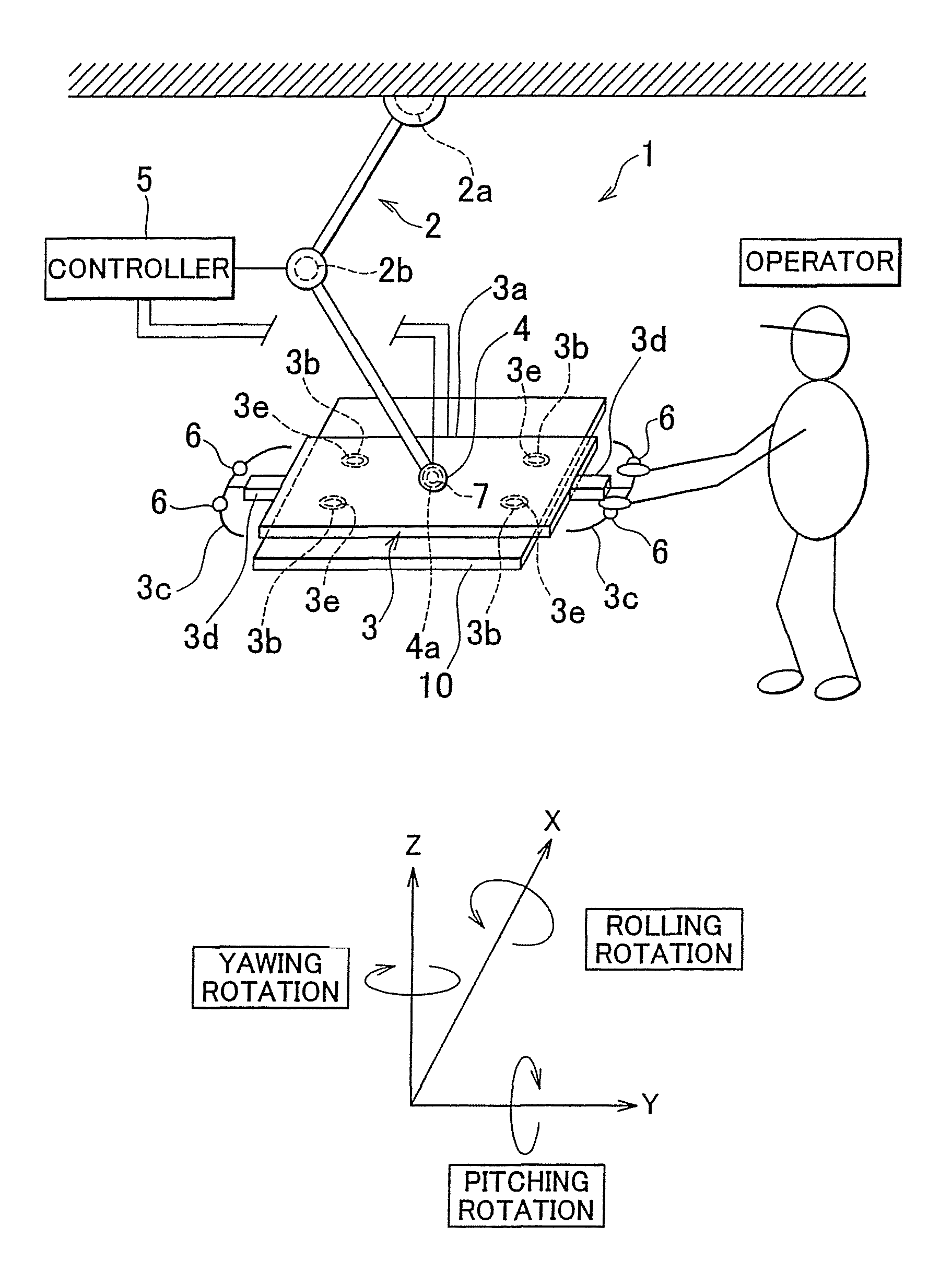
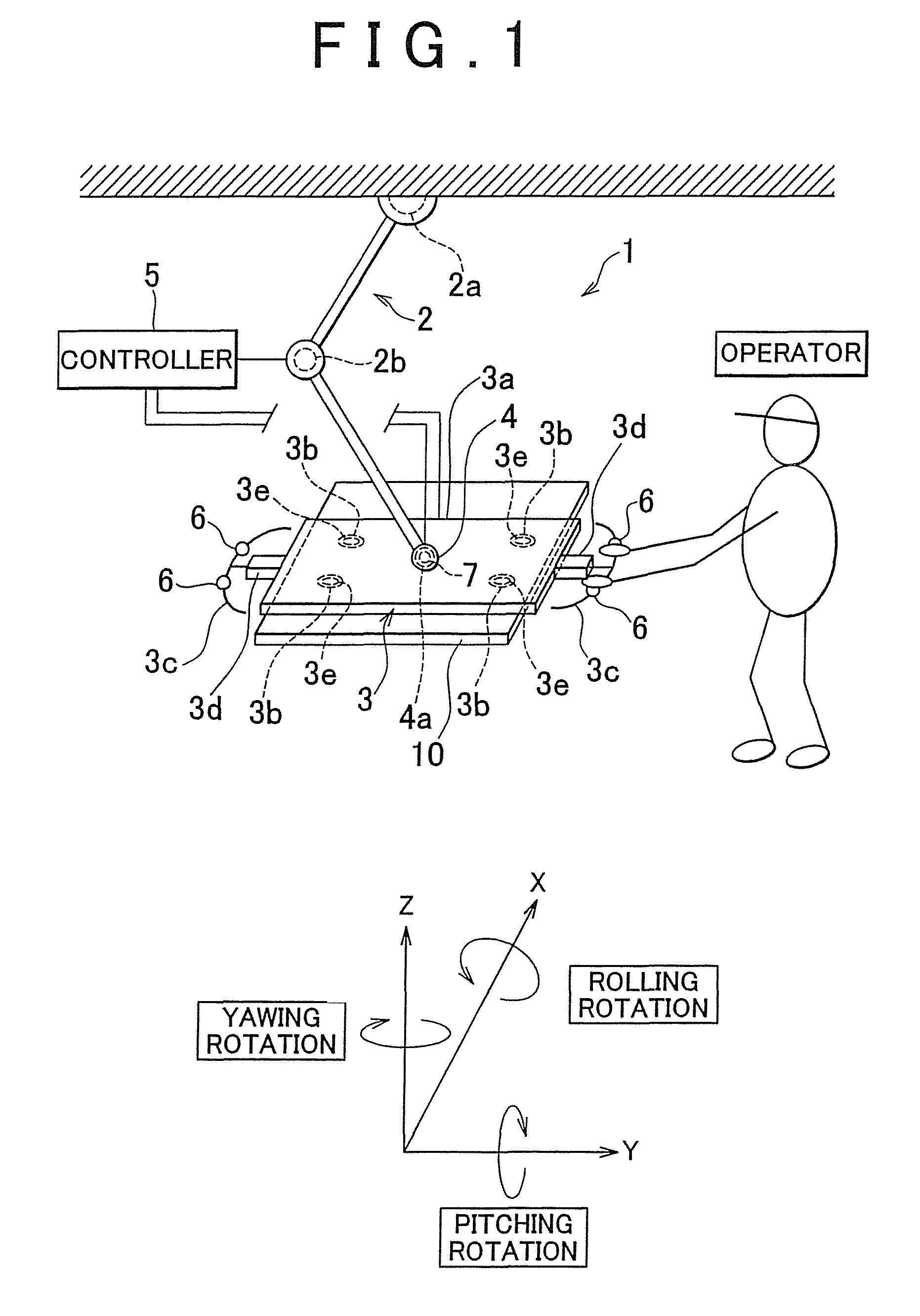
[0034]First, the overall constitution of a power assist apparatus 1 according to an embodiment of the invention will be described using FIGS. 1 to 3. FIG. 1 is a schematic diagram showing the overall constitution of the power assist apparatus according to an embodiment of the invention. FIG. 2 is a schematic plan view and a schematic side view showing a workpiece holding device according to the embodiment of the invention. FIG. 3 is a schematic diagram showing a connection condition of a controller according to the embodiment of the invention. Note that for ease of description, it is assumed that the power assist apparatus is provided on an XYZ coordinate system shown in FIG. 1, wherein rotation about the X axis denotes rolling rotation, rotation about the Y axis denotes pitching rotation, and rotation about the Z axis denotes yawing rotation. As shown in FIG. 1, the power assist apparatus 1 according to this embodiment includes an articulated robot 2, a workpiece holding device 3, ...


PUM

PropertyMeasurementUnit
degrees of freedomaaaaaaaaaa
rotation angleaaaaaaaaaa
poweraaaaaaaaaa

Abstract

If the rotation angle in a rotation direction allowed by a joint portion detected by the angle sensor is no more than a predetermined lower limit or no less than a predetermined upper limit, the controller maintains the released state of the brake mechanism so that the rotation of the workpiece in the direction is not restricted.

Description

[0001]This is a 371 national phase application of PCT / IB2009 / 005472 filed 22 Apr. 2009, claiming priority to Japanese Patent Application No. 2008-114245 filed 24 Apr. 2008, the contents of which are incorporated herein by reference.BACKGROUND OF THE INVENTION[0002]1. Field of the Invention[0003]The invention relates to a power assist apparatus and a control method for a power assist apparatus.[0004]2. Description of the Related Art[0005]In manufacturing sites and the like for manufacturing industrial products, a power assist apparatus is used as an apparatus for assisting an operator in the conveyance of heavy loads (workpieces). A workpiece attachment operation includes conveyance and positioning of the workpiece, but when the workpiece is conveyed cooperatively by the operator and the power assist apparatus, the power required to convey the workpiece can be provided by the power assist apparatus. Moreover, by teaching the power assist apparatus, positioning of the workpiece can be...

Claims


Application Information

Patent Timeline
Patent Type & Authority Patents(United States)
IPC IPC(8): B66F19/00
CPCB25J9/1674B25J19/0004B66C1/0256B66C23/005B66C1/0243Y10T29/53961
Inventor MURAYAMA, HIDEYUKI
Owner TOYOTA JIDOSHA KK
Why Eureka
Try Eureka