Joint structure of iron framework and coupling member for connecting rectangular steel beam to rectangular steel column

a technology of connecting member and iron frame, which is applied in the direction of joists, girders, trusses, etc., can solve the problems of weakening and lowering workability, and achieve the effects of easy connection, enhanced workability and adjustable strength

Inactive Publication Date: 2006-11-30
HIRAGAKI MINORU
View PDF9 Cites 69 Cited by
  • Summary
  • Abstract
  • Description
  • Claims
  • Application Information

AI Technical Summary

Benefits of technology

[0022] The strength can be adjusted by changing the length, width, and the like of each slit, or by providing a plurality of slits.
[0023] Further, according to the joint structure of iron framework claimed in claim 3, in addition to the advantage of the invention claimed in claim 1, the following advantage is produced. That is, the upper surface of the hollow rectangular steel beam is formed with a hand insertion hole of a size that allows a hand to enter therein. Thus, the U-shaped receiving member and the hollow rectangular steel beam are easily connected to each other by the bottom bolt and the bottom nut via the bottom bolt hole and the bottom surface bolt hole, by the left bolt and the left nut via the right bolt hole and the right side surface bolt hole, and by the right bolt and the right nut via the right bolt and the right side surface bolt.
[0024] Further, according to the joint structure of iron framework claimed in claim 4, in addition to the advantage of the invention claimed in claim 1 described above, the following advantage is produced. That is, when the height of the side surface of the hollow rectangular steel beam is large, the left side surface of the hollow rectangular steel beam is formed with a hand insertion hole of rectangular beam's left side surface of a size that allows a hand to enter therein. At the same time, the right side surface of the hollow rectangular steel beam is formed with a hand insertion hole of rectangular beam's right side surface of a size that allows a hand to enter therein. The U-shaped receiving member and the hollow rectangular can be easily connected to each other by the left bolt and the left nut via the left bolt hole and left side surface bolt hole, and by the right bolt and the right nut via the right bolt hole and the right side surface bolt hole. As a result, the workability can be enhanced.
[0025] Further, according to the joint structure of iron framework claimed in claim 5, in addition to the advantage of the invention claimed in claim 1 above, the following advantage is produced. That is, since the lid is formed with a slit and the lid is firmly attached to the hollow rectangular steel beam via the slit, the lid can be firmly attached to the hollowing rectangular steel beam easily and strongly.
[0027] Further, according to the joint member for connecting a rectangular steel beam to a rectangular steel column claimed in claim 11, the rectangular cylinder of the joint member is fitted to the outer periphery of the hollow rectangular steel column and is firmly attached to the hollow rectangular steel column without cutting some midpoint of the hollow rectangular steel column as in prior arts. As a result, the workability is enhanced. In addition, since the beam is a hollow rectangular steel beam unlike a conventional beam having a H-shaped cross section, the joint member produces an advantage that the strength against the lateral loading is increased.

Problems solved by technology

However, this joint structure of iron framework requires cutting of some midpoint of a hollow rectangular steel column, and this cutting operation lowers the workability.
In addition, the H-shaped steel beam is connected to the hollow rectangular steel column, and this beam has a problem that it is weak against a load applied thereto from its side direction (i.e. horizontal load).

Method used


Image

  • Joint structure of iron framework and coupling member for connecting rectangular steel beam to rectangular steel column
  • Joint structure of iron framework and coupling member for connecting rectangular steel beam to rectangular steel column
  • Joint structure of iron framework and coupling member for connecting rectangular steel beam to rectangular steel column

Examples


Embodiment Construction

[0047] A joint structure of iron framework and a coupling member for connecting a rectangular steel beam to a rectangular steel column according to an embodiment of the present invention will be described with reference to drawings.

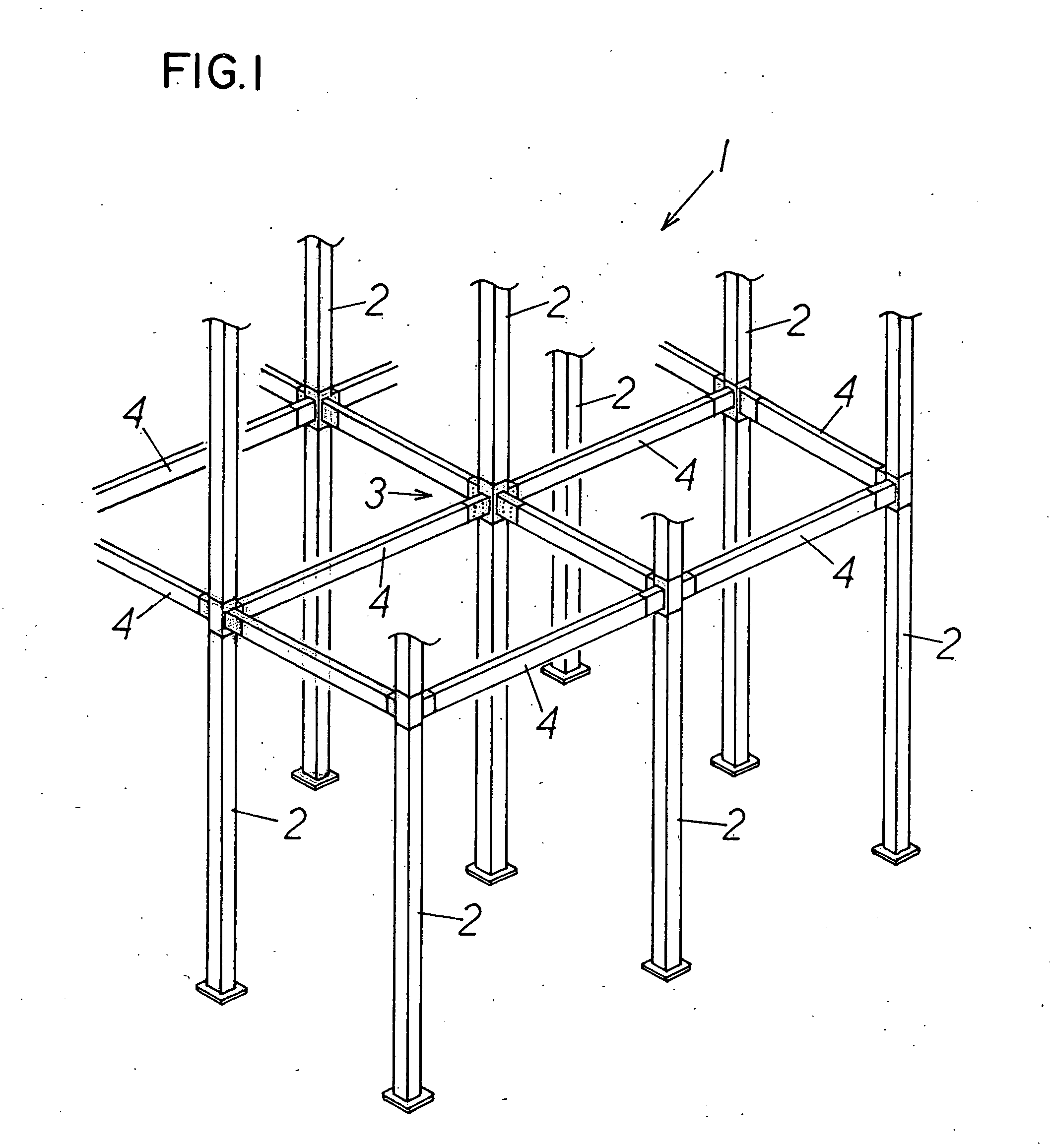
[0048] A reference numeral 1 shown in FIG. 1 denotes an iron framework structure constituted by connecting a hollow rectangular beam 4 to a hollow rectangular steel column 2 via a coupling member 3.

[0049] An outer shape of a cross-section crossing over a longitudinal direction of the hollow rectangular steel column 2 and an outer shape of a cross-section crossing over a longitudinal direction of the hollow rectangular steel beam 4 respectively assume a rectangular shape.

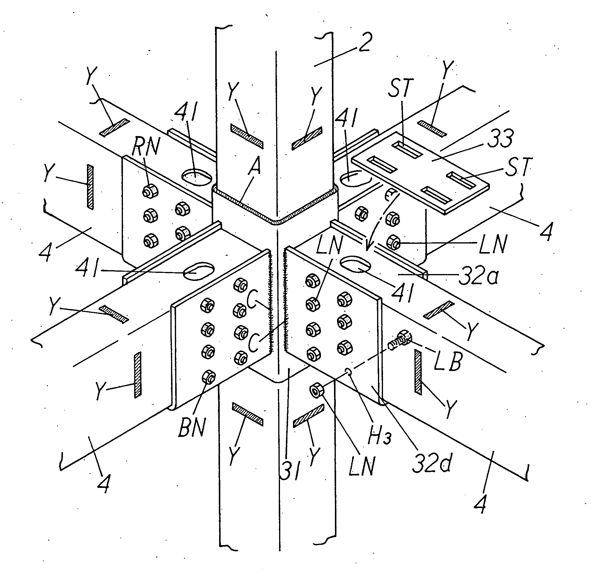
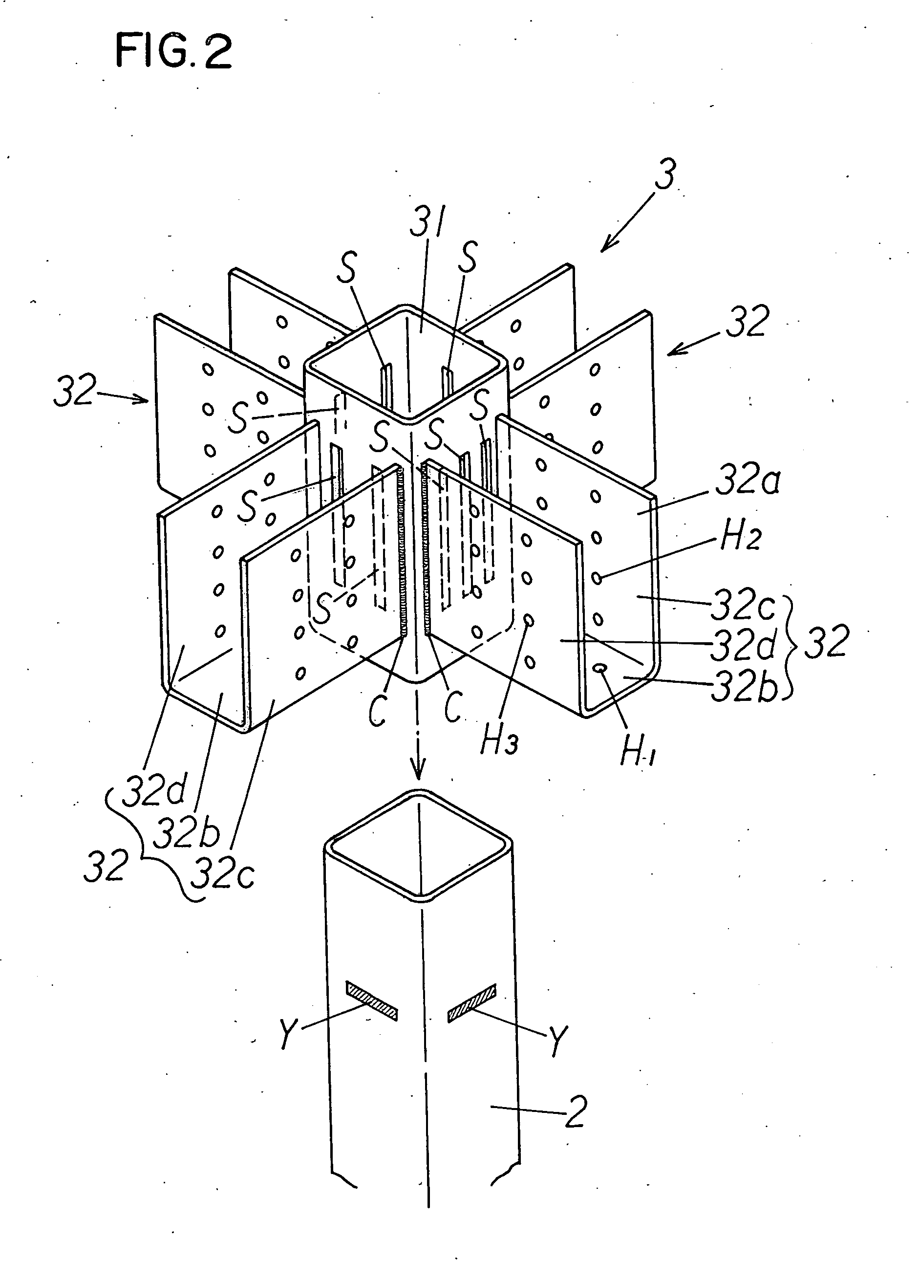
[0050] The coupling member 3 is used for connecting the hollow rectangular steel beam 4 to the hollow rectangular steel column 2. As shown in FIGS. 2 to 8, the coupling member 3 schematically includes: a rectangular cylinder (substantially rectangular sleeve) 31; U-shaped receiving memb...


PUM


Abstract

The present invention provides a joint structure of iron framework capable of enhancing workability and strength. The joint structure of iron framework 1 is a joint structure of iron framework for connecting a hollow rectangular steel beam 4 to a hollow rectangular steel column 2 via a coupling member 3. The coupling member 3 includes: a rectangular cylinder 31 fitted to an outer periphery of the hollow rectangular steel column 4 and firmly attached to the hollow rectangular steel column 4; a U-shaped receiving member 4 provided to a side surface of the rectangular cylinder 31 for connecting the hollow rectangular steel beam 4, the U-shaped receiving member 32 having a bottom portion 32b protruded from the side surface of the rectangular cylinder 31, having a U-shaped opening portion 32 located to face upward, having a U-shaped end surface firmly attached to the side surface of the rectangular cylinder 31; and a lid 33 firmly attached to the U-shaped receiving member 32 in a state of covering the upper surface of the hollow rectangular steel beam 4 mounted in the U-shaped receiving member 32.

Description

BACKGROUD OF THE INVENTION [0001] 1. Field of the Invention [0002] The present invention relates to a joint structure of iron framework and a coupling member for connecting rectangular steel beam to rectangular steel column, and specifically, relates to a joint structure of iron framework and a coupling member for connecting a rectangular steel beam to a rectangular steel column capable of enhancing workability and strength. [0003] 2. Description of the Related Art [0004] Conventionally, there is a joint structure of iron framework for connecting an H-shaped steel beam to a hollow rectangular steel column (for example, see non-patent document 1). [0005] In this joint structure, some midpoint of a hollow rectangular steel column is cut. Then, an H-shaped steel beam is connected to the hollow rectangular steel column by welding via a member called diaphragm so as to enhance the rigidity of the joint therebetween. [0006] However, this joint structure of iron framework requires cutting ...

Claims


Application Information

Patent Timeline
Patent Type & Authority Applications(United States)
IPC IPC(8): E04C3/02
CPCE04B1/2403E04B5/43E04B2001/2406E04B2001/2418E04C2003/0465E04B2001/2451E04B2001/2457E04C2003/043E04B2001/2421
Inventor HIRAGAKI, MINORU
Owner HIRAGAKI MINORU
Why Eureka
Try Eureka