Adapter For Mounting A Tool On An Oscillating Drive

a technology of adapter and oscillating drive, which is applied in the direction of turning apparatus, grinding machines, chucks, etc., can solve the problems of increasing stocking costs, increasing costs, and a lesser degree of cost reduction, so as to reduce the variety of tools and reduce costs

Active Publication Date: 2010-03-04
C & E FEIN GMBH & CO KG
View PDF13 Cites 103 Cited by
  • Summary
  • Abstract
  • Description
  • Claims
  • Application Information

AI Technical Summary

Benefits of technology

[0014]This has the effect to clearly reduce the variety of tools and to reduce costs accordingly.

Problems solved by technology

The great variety of systems available in the market, with respect to the mounting opening and the matching mounting section of the drive shaft, clearly increase the required variety for such wearing parts, with the result of increased costs due to different packings, increased stocking costs or a lesser degree of cost reduction achievable in mass production.

Method used


Image

  • Adapter For Mounting A Tool On An Oscillating Drive
  • Adapter For Mounting A Tool On An Oscillating Drive
  • Adapter For Mounting A Tool On An Oscillating Drive

Examples


Embodiment Construction

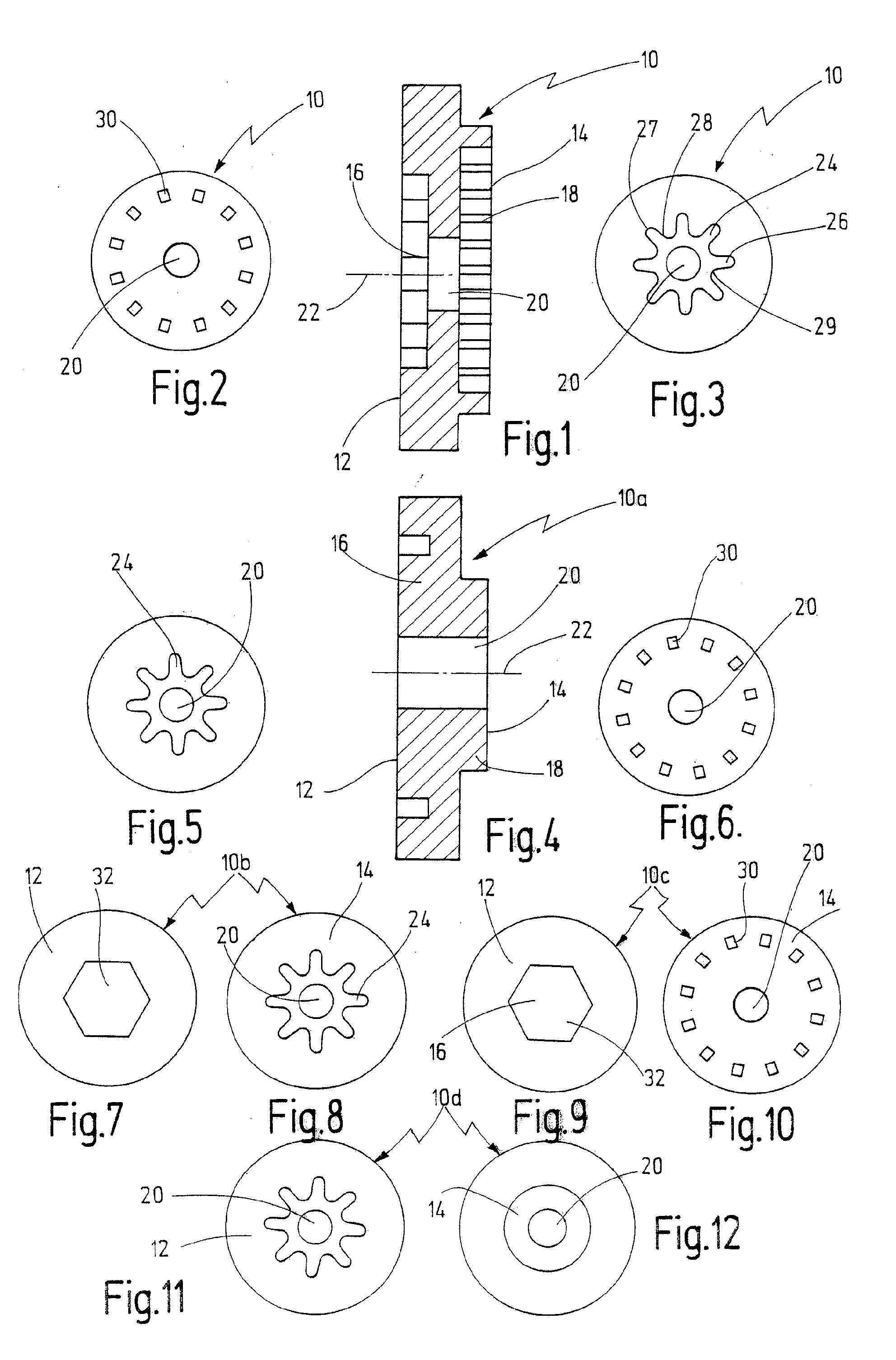
[0038]In FIG. 1, a first embodiment of an adapter according to the invention is indicated generally by reference numeral 10. FIG. 1 shows a cross-sectional view of the adapter 10 in enlarged scale. The adapter 10 has a generally cylindrical shape in the form of a relatively flat disk with a center axis 22. The adapter is passed by a cylindrical opening 20. On its machine end 12 facing the oscillating drive, the adapter 10 is provided with a first receptacle 16 in the form of a depression. On its opposite tool end 14 facing the tool, the adapter 10 is provided with a second receptacle 18, configured as an outwardly projecting raised portion, to allow a tool with a correspondingly shaped opening to be mounted. As can be seen in FIG. 3, the form of the first receptacle 16 has a total of eight outwardly extending convex projections 26, each having a rounded tip 27 and being connected with neighboring projections 26 via rounded concave lateral flanks 28. The entire arrangement is symmetr...


PUM


Abstract

An adapter is disclosed for mounting a tool on an oscillating drive having a drive shaft that can be driven to oscillate about its longitudinal axis, wherein the adapter is passed by a central opening, and has at its drive end at least one positive-locking element for positive connection with the tool, the positive-locking element having the shape of a regular polygon, or a plurality of positive-locking elements arranged on a circle concentric to the center axis, or a plurality of outwardly extending convex projections having rounded tips and being connected with neighboring projections via rounded concave lateral flanks, wherein the positive-locking elements on the drive end are configured for positive-locking connection with a matching positive-locking counter-element on the drive shaft, and wherein the adapter has a second receptacle on its tool end for effecting connection with a tool having a shape different from the first receptacle and being configured as a circle, or as a plurality of positive-locking elements arranged along a circle concentric to the center axis, or as plurality of outwardly extending convex projections with rounded tips and being connected with neighboring projections via rounded concave lateral flanks.

Description

BACKGROUND OF THE INVENTION[0001]The present invention relates to an adapter for mounting a tool on an oscillating drive having a drive shaft that can be driven to oscillate about its longitudinal axis, wherein the adapter comprises a drive end facing the drive shaft and a tool end facing the tool and is passed by a central opening, wherein the adapter has a first receptacle on the drive end which comprises at least one positive-locking element for connection with the tool, and wherein the adapter has a second receptacle on its tool end facing the tool, for connection with a tool, whose shape differs from that of the first receptacle.[0002]An adapter of that kind is known from U.S. Pat. No. 6,945,862 B2.[0003]The respective adapter shows on its tool side a depression provided with a plurality of outwardly extending convex projections, each having a rounded tip and being connected with neighboring projections via rounded concave lateral flanks. On its machine end, facing the oscillat...

Claims


Application Information

Patent Timeline
Patent Type & Authority Applications(United States)
IPC IPC(8): B24B23/00
CPCB23B31/008B24B45/006B24B23/04B23B2231/04
Inventor GRUNIKIEWICZ, PETER
Owner C & E FEIN GMBH & CO KG
Why Eureka
Try Eureka