
Chain locator

a chain locator and chain technology, applied in the direction of rail brake actuation, railway braking system, engine controller, etc., can solve the problems of increasing maintenance costs, difficulty in detecting if the brake system is actually fully released, and wheel damage contributing a great deal to maintenance costs, so as to improve the braking system

Active Publication Date: 2010-03-11
AMSTED RAIL CO INC
View PDF29 Cites 8 Cited by
  • Summary
  • Abstract
  • Description
  • Claims
  • Application Information

AI Technical Summary

Benefits of technology

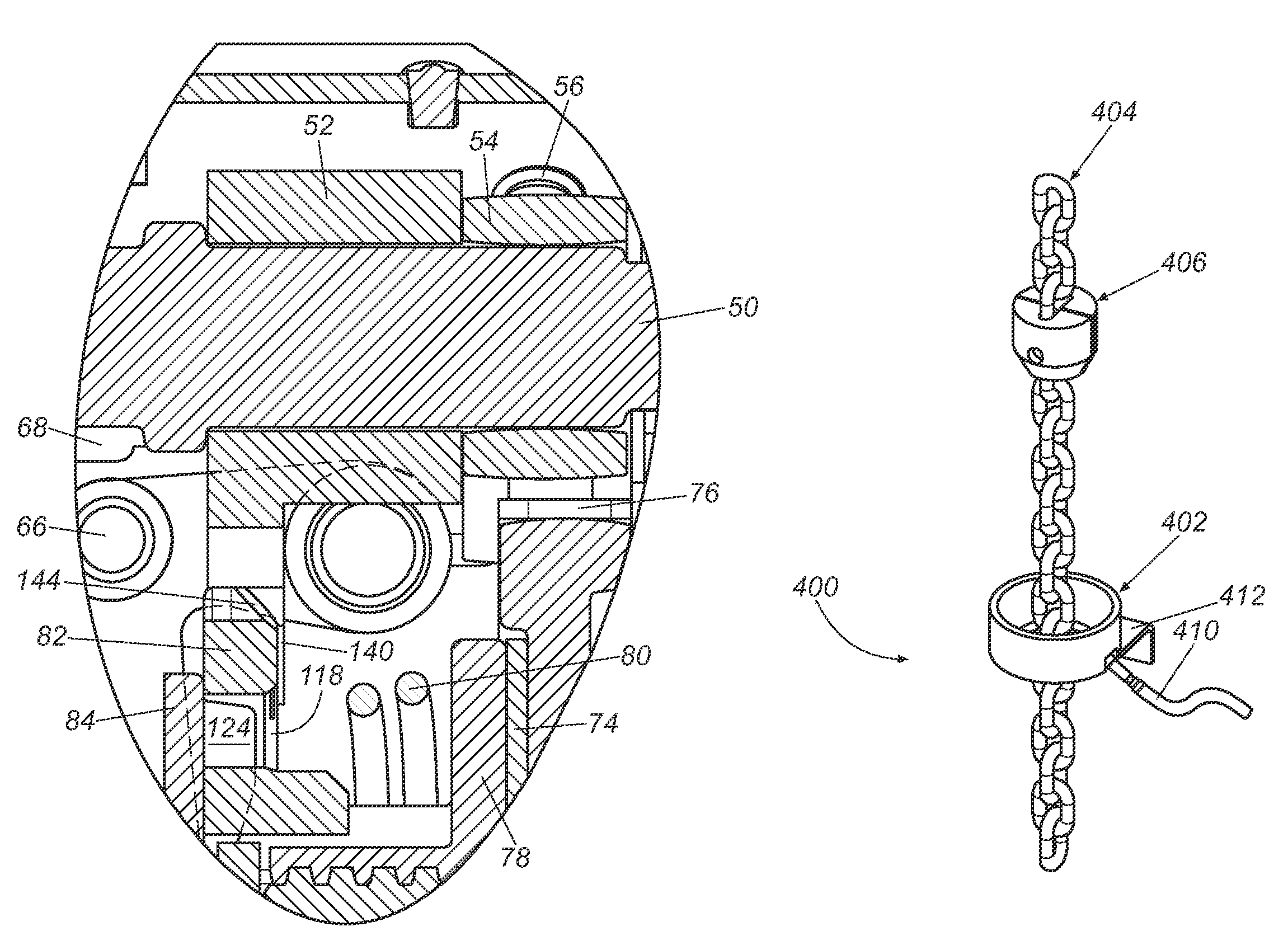
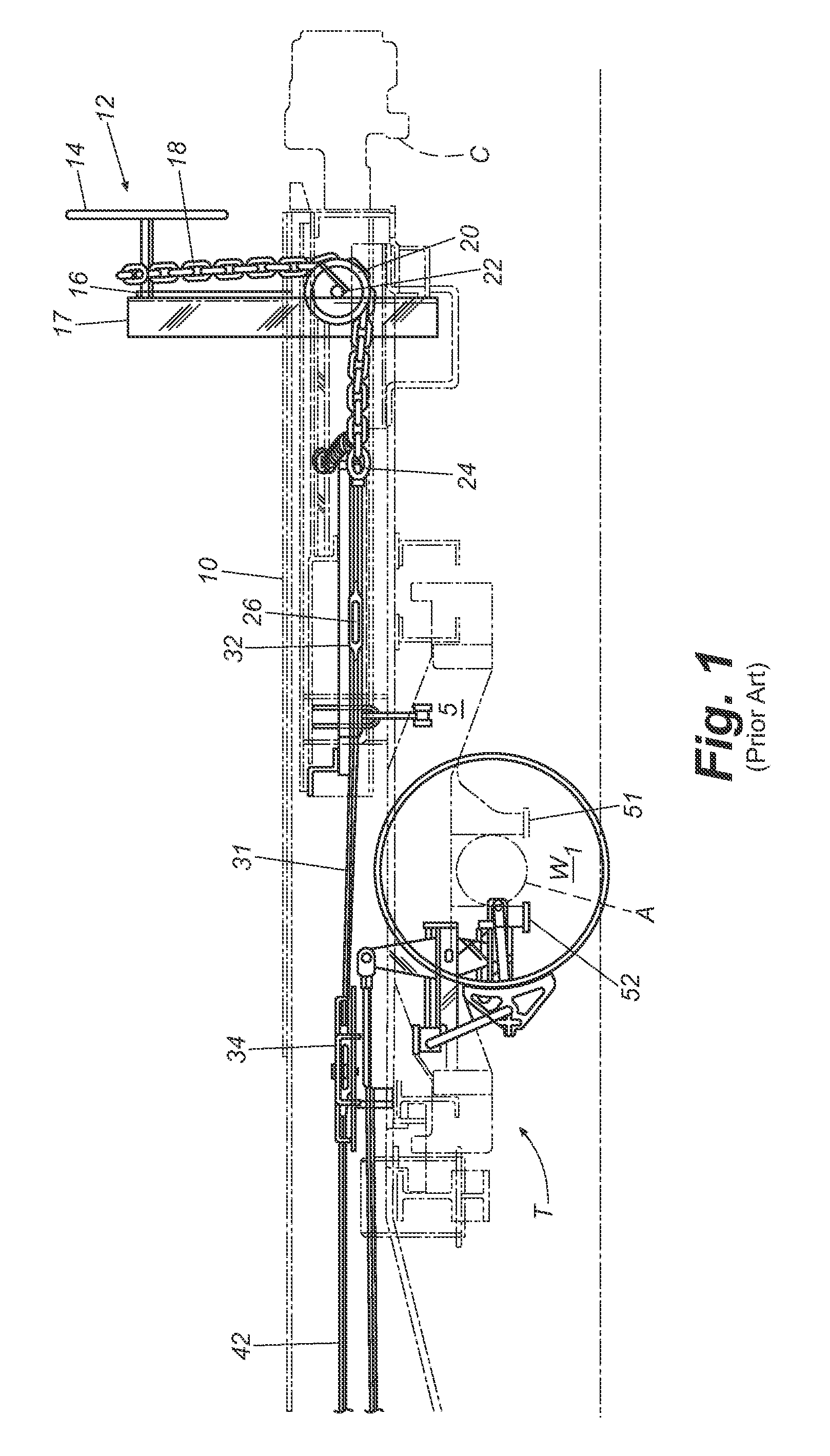
[0006]The present invention recognizes and addresses disadvantages of prior art constructions and methods, and it is an object of the present invention to provide an improved braking system. This and other objects may be achieved by a brake mechanism having a chain locator comprising a chain coupled between a braking mechanism and a railway car brake system, a marker releasably secured to the chain, and a sensor coupled to the railway car proximate the chain for detecting the state of the railway car brake system. The chain is moveable between a first position in which the marker is not sensed by the sensor, and a second position in which the sensor detects the marker. In some embodiments, the sensor is a proximity sensor. In other embodiments, the sensor is a switch type sensor.

Problems solved by technology

Wheel damage contributes a great deal to maintenance costs associated with railway freight cars.
Unreleased handbrakes contribute to most damage on freight car wheels.
However, one problem with these systems is that it is difficult to detect if the brake system is actually fully released.
However, these solutions present additional problems and fail to provide an automated brake release solution.

Method used


Image

  • Chain locator
  • Chain locator
  • Chain locator

Examples


Embodiment Construction

[0039]Reference will now be made in detail to presently preferred embodiments of the invention, one or more examples of which are illustrated in the accompanying drawings. Each example is provided by way of explanation, not limitation, of the invention. It is to be understood by one of ordinary skill in the art that the present discussion is a description of exemplary embodiments only, and is not intended as limiting the broader aspects of the present invention, which broader aspects are embodied in the exemplary constructions. In fact, it will be apparent to those skilled in the art that modifications and variations can be made in the present invention without departing from the scope and spirit thereof. For instance, features illustrated or described as part of one embodiment may be used on another embodiment to yield a still further embodiment. Thus, it is intended that the present invention covers such modifications and variations as come within the scope of the appended claims ...


PUM


Abstract

A brake mechanism having a chain locator comprises a chain coupled between a braking mechanism and a railway car brake system, a marker is releasably secured to the chain, and a sensor is coupled to the railway car proximate the chain for detecting the state of the railway car brake system. The chain is moveable between a first position in which the marker is not sensed by the sensor, and a second position in which the sensor detects the marker.

Description

CLAIM OF PRIORITY[0001]The present application claims priority to U.S. Provisional Patent Application Ser. No. 61 / 096,046, filed Sep. 11, 2008, entitled Remote Hand Brake, Power Sheave and Chain Locator, the entire disclosure of which is incorporated by reference herein.FIELD OF THE INVENTION[0002]The present invention relates generally to railcar brake systems. More particularly, the present invention relates to a chain locator for use with a railway car brake system.BACKGROUND[0003]Wheel damage contributes a great deal to maintenance costs associated with railway freight cars. Unreleased handbrakes contribute to most damage on freight car wheels. That is, if the handbrake is left in the applied position and an engine then pulls the railway car, the wheel will not rotate thereby causing flat spots to form on the area of the wheel in contact with the rail.[0004]It is well known in the art of railroad cars to equip railcars with a manual brake system that is actuated by a manually tu...

Claims


Application Information

Patent Timeline
Patent Type & Authority Applications(United States)
IPC IPC(8): F16D66/00
CPCB61H13/04Y10T477/743F16D2066/003
Inventor MICHEL, MARKHEAD, THOMAS STUART
Owner AMSTED RAIL CO INC
Learn More